


98
115895B System Installation Manual
SERIAL TO ETHERNET ADAPTER OPTION SECTION
Myers Emergency Power Systems
–
Emergency Lighting Central Inverter
Serial to Ethernet Communication Interface
–
QuickStart Guide
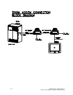
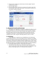
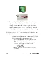
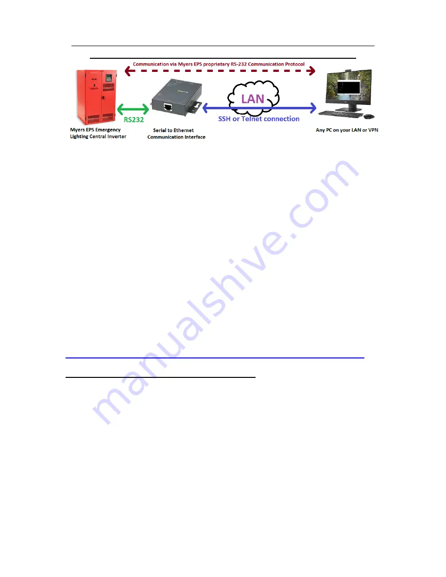
The Serial to Ethernet Communication Interface primarily allows you to monitor
and control your Myers EPS Emergency Lighting Central Inverter over an SSH connection
(on port 2222) using the Myers EPS RS-232 Communication Protocol. The SSH port
number can be configured, or if you choose, Telnet may be selected instead of SSH.
The Serial to Ethernet Communication Interface is based on the IOLAN SDG1
product by Perle, which has many features including the ability to install a Virtual Com
Port (VCP) driver on a Windows PC, create a virtual COM port, and make a
‘
serial tunnel
’
through your LAN from that virtual COM port to your inverter to exactly mimic being
directly connected from your PC to the inverter with a serial (RS232) cable.
This QuickStart Guide only describes a subset of the features in the IOLAN SDG1:
1.
Basic network configuration
2.
Communicating with your inverter via an SSH client
3.
Changing the port number
4.
Changing the protocol from SSH to Telnet
5.
Factory Reset
For more information on instead using the Virtual Com Port feature or other
features, please reference the IOLAN Secure User
’
s Guide, Perle Document Part Number
5500431-10, currently hosted at the following URL:
https://www.perle.com/support_services/documentation_pdfs/iolan_scg-sdg-stg_ug.pdf
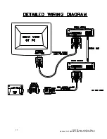
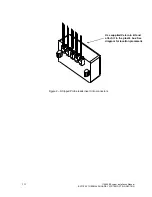
1 - Basic Network Configuration for your LAN
The default static IP address of the IOLAN SDG1 is
10.16.0.67
(Subnet Mask
255.240.0.0
). To set it to the correct network settings for your LAN:
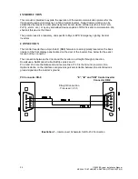
1.
Connect a direct Ethernet cable connection between a PC and the IOLAN SDG1.
It doesn
’
t matter if the Ethernet cable is a straight-through or crossover cable.
2.
Set the wired LAN interface of the connected PC to a static IP address in the
10.16.0.XXX range (where XXX is any number from 1 to 254,
except 67
). Set the
subnet mask to 255.240.0.0. It doesn
’
t matter what you set the Default Gateway
or DNS Server settings to. Note that you should save your previous settings for
the PC so that you can remember how to restore them when you
’
re done. Note
also that the instructions to change the IP address, subnet, etc. will vary
depending on which version of which Operating System is on your PC. If you are
not aware of how to do so, please Google how to do so for your Operating
System and version. Note also that if your PC has multiple network interfaces
Содержание Illuminator Supernova Series
Страница 16: ...15 115895B System Installation Manual Figure 5 2 AC Connections for 6 25 k W 7 5 kW systems ...
Страница 17: ...16 115895B System Installation Manual Figure 5 3 AC Connections for 10 kW 16 7 kW systems ...
Страница 30: ...115895B System Installation Manual PART II OPTIONS MANUALS Section continues on next page ...
Страница 95: ...94 115895B System Installation Manual SERIAL TO ETHERNET ADAPTER OPTION SECTION ...
Страница 96: ...95 115895B System Installation Manual SERIAL TO ETHERNET ADAPTER OPTION SECTION ...
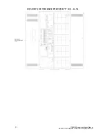
Страница 113: ...112 115895B System Installation Manual DRAWINGS SECTION PART III DRAWINGS Drawings section continues on next page ...
Страница 114: ...113 115895B System Installation Manual DRAWINGS SECTION ...
Страница 115: ...114 115895B System Installation Manual DRAWINGS SECTION ...
Страница 116: ...115 115895B System Installation Manual DRAWINGS SECTION ...
Страница 117: ...116 115895B System Installation Manual DRAWINGS SECTION ...
Страница 118: ...117 115895B System Installation Manual DRAWINGS SECTION ...
Страница 119: ...118 115895B System Installation Manual DRAWINGS SECTION ...
Страница 120: ...119 115895B System Installation Manual DRAWINGS SECTION ...
Страница 121: ...120 115895B System Installation Manual DRAWINGS SECTION ...
Страница 122: ...121 115895B System Installation Manual DRAWINGS SECTION ...
Страница 123: ...122 115895B System Installation Manual DRAWINGS SECTION ...
Страница 124: ...123 115895B System Installation Manual DRAWINGS SECTION ...
Страница 125: ...124 115895B System Installation Manual DRAWINGS SECTION ...
Страница 126: ...125 115895B System Installation Manual DRAWINGS SECTION ...
Страница 127: ...126 115895B System Installation Manual DRAWINGS SECTION ...
Страница 128: ...127 115895B System Installation Manual DRAWINGS SECTION ...
Страница 129: ...128 115895B System Installation Manual DRAWINGS SECTION ...
Страница 130: ...129 115895B System Installation Manual DRAWINGS SECTION ...
Страница 131: ...130 115895B System Installation Manual Notes ...


