


110
115895B System Installation Manual
BATTERY THERMAL RUNAWAY SYSTEM OPTION SECTION
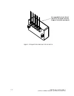
b. The power and error signal connections will need to be wired from the
first Temperature Sensor PCB to the next Temperature sensor PCB
via the wire supplied in the kit. This will follow the instruction in item a
until the last temperature sensor pcb has been wired.
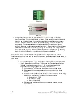
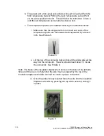
c. The temperature probes are installed following the instruction below:
i. Make sure that the stripped wire is removed and ends of the
temperature probe are full insulated and separated by at least 1
inch. See Picture 5.
Picture 5
ii. Lift the top of the connector fully and insert the probe wire all the
way into the connector. The wire should in
sert about ½” inside
the connector. See Picture 6.
Note: The blade of the insulation displacement knife is in the back of the left side
hole and if the top is not fully lifted the wire may be stopped by the top of the
insulation displacement knife and will not make a proper connection.
iii. Once the probe ifs fully inserted force the wire into the insulation
displacement knife by pressing the top down securely locking it
in place.
Figure 6
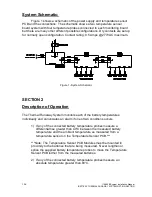
Содержание Illuminator Supernova Series
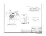
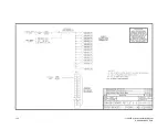
Страница 16: ...15 115895B System Installation Manual Figure 5 2 AC Connections for 6 25 k W 7 5 kW systems ...
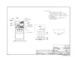
Страница 17: ...16 115895B System Installation Manual Figure 5 3 AC Connections for 10 kW 16 7 kW systems ...
Страница 30: ...115895B System Installation Manual PART II OPTIONS MANUALS Section continues on next page ...
Страница 95: ...94 115895B System Installation Manual SERIAL TO ETHERNET ADAPTER OPTION SECTION ...
Страница 96: ...95 115895B System Installation Manual SERIAL TO ETHERNET ADAPTER OPTION SECTION ...
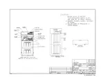
Страница 113: ...112 115895B System Installation Manual DRAWINGS SECTION PART III DRAWINGS Drawings section continues on next page ...
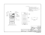
Страница 114: ...113 115895B System Installation Manual DRAWINGS SECTION ...
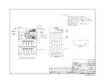
Страница 115: ...114 115895B System Installation Manual DRAWINGS SECTION ...
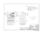
Страница 116: ...115 115895B System Installation Manual DRAWINGS SECTION ...
Страница 117: ...116 115895B System Installation Manual DRAWINGS SECTION ...
Страница 118: ...117 115895B System Installation Manual DRAWINGS SECTION ...
Страница 119: ...118 115895B System Installation Manual DRAWINGS SECTION ...
Страница 120: ...119 115895B System Installation Manual DRAWINGS SECTION ...
Страница 121: ...120 115895B System Installation Manual DRAWINGS SECTION ...
Страница 122: ...121 115895B System Installation Manual DRAWINGS SECTION ...
Страница 123: ...122 115895B System Installation Manual DRAWINGS SECTION ...
Страница 124: ...123 115895B System Installation Manual DRAWINGS SECTION ...
Страница 125: ...124 115895B System Installation Manual DRAWINGS SECTION ...
Страница 126: ...125 115895B System Installation Manual DRAWINGS SECTION ...
Страница 127: ...126 115895B System Installation Manual DRAWINGS SECTION ...
Страница 128: ...127 115895B System Installation Manual DRAWINGS SECTION ...
Страница 129: ...128 115895B System Installation Manual DRAWINGS SECTION ...
Страница 130: ...129 115895B System Installation Manual DRAWINGS SECTION ...
Страница 131: ...130 115895B System Installation Manual Notes ...


