


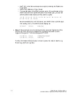


62
115895B System Installation Manual
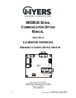
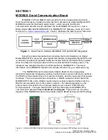
MODBUS SERIAL COMMUNICATION OPTION SECTION
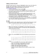
Setting a Custom User ID
Setting a Custom User ID is done with MODBUS Function Code 0x15 (Write File
Record). See the description of the Write File Record function code in the
MODBUS Application Protocol Specification document from
http://www.modbus.org/specs.php
•
Sub Request Reference Type must be
0x06
•
Sub Request File Number must be
0x0004
. Note: File numbers 1, 2 and 3
are used for Alarm Log, Event Log and Test Log file records which are
Read Only (see Section 7).
•
Sub Request Record Number must be 0x0000 through 0x001F to start
writing at any of the 32 bytes of the Custom User ID string. It is
recommended that you start writing at Record Number 0x0000 and write
all 32 bytes (or less) in one MODBUS packet/frame.
•
The Sub Request Record Data occurs in 16-bit
‘byte pairs’. The MODBUS
Communication Option Board will always ignore the first (most significant)
byte of a pair, and will only store the second.
Example
You wish to set the Custom User ID string to
“2nd Floor West Emergency Lights”.
•
Step 1
: Converted to ASCII codes in hexadecimal, this string is:
32 6e 64 20 46 6c 6f 6f 72 20 57 65 73 74 20 45
6d 65 72 67 65 6e 63 79 20 4c 69 67 68 74 73 00
•
Step 2
: As stated above, the MODBUS Communication Option Board
ignores the most significant byte of each byte pair. After translating the
string to byte pairs, we have:
00 32 00 6e 00 64 00 20 00 46 00 6c 00 6f 00 6f
00 72 00 20 00 57 00 65 00 73 00 74 00 20 00 45
00 6d 00 65 00 72 00 67 00 65 00 6e 00 63 00 79
00 20 00 4c 00 69 00 67 00 68 00 74 00 73 00 00
•
Step 3
: The entire MODBUS PDU (Protocol Data Unit) would therefore
be:
15 47 06 00 04 00 00 00 20
00 32 00 6e 00 64 00 20 00 46 00 6c 00 6f 00 6f
00 72 00 20 00 57 00 65 00 73 00 74 00 20 00 45
00 6d 00 65 00 72 00 67 00 65 00 6e 00 63 00 79
00 20 00 4c 00 69 00 67 00 68 00 74 00 73 00 00
Where:
o
0x15 is the MODBUS Function Code (Write File Record)
o
0x47 (71) is the size of the remainder of the PDU
o
0x06 is the Sub Request Reference Type (fixed)
o
0x0004 is the Sub Request File Number
o
0x0000 is the Sub Request Record Number
o
0x00020 is the Sub Request Record Length (in units of
‘2 byte
words
’)
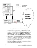
Содержание Illuminator Supernova Series
Страница 16: ...15 115895B System Installation Manual Figure 5 2 AC Connections for 6 25 k W 7 5 kW systems ...
Страница 17: ...16 115895B System Installation Manual Figure 5 3 AC Connections for 10 kW 16 7 kW systems ...
Страница 30: ...115895B System Installation Manual PART II OPTIONS MANUALS Section continues on next page ...
Страница 95: ...94 115895B System Installation Manual SERIAL TO ETHERNET ADAPTER OPTION SECTION ...
Страница 96: ...95 115895B System Installation Manual SERIAL TO ETHERNET ADAPTER OPTION SECTION ...
Страница 113: ...112 115895B System Installation Manual DRAWINGS SECTION PART III DRAWINGS Drawings section continues on next page ...
Страница 114: ...113 115895B System Installation Manual DRAWINGS SECTION ...
Страница 115: ...114 115895B System Installation Manual DRAWINGS SECTION ...
Страница 116: ...115 115895B System Installation Manual DRAWINGS SECTION ...
Страница 117: ...116 115895B System Installation Manual DRAWINGS SECTION ...
Страница 118: ...117 115895B System Installation Manual DRAWINGS SECTION ...
Страница 119: ...118 115895B System Installation Manual DRAWINGS SECTION ...
Страница 120: ...119 115895B System Installation Manual DRAWINGS SECTION ...
Страница 121: ...120 115895B System Installation Manual DRAWINGS SECTION ...
Страница 122: ...121 115895B System Installation Manual DRAWINGS SECTION ...
Страница 123: ...122 115895B System Installation Manual DRAWINGS SECTION ...
Страница 124: ...123 115895B System Installation Manual DRAWINGS SECTION ...
Страница 125: ...124 115895B System Installation Manual DRAWINGS SECTION ...
Страница 126: ...125 115895B System Installation Manual DRAWINGS SECTION ...
Страница 127: ...126 115895B System Installation Manual DRAWINGS SECTION ...
Страница 128: ...127 115895B System Installation Manual DRAWINGS SECTION ...
Страница 129: ...128 115895B System Installation Manual DRAWINGS SECTION ...
Страница 130: ...129 115895B System Installation Manual DRAWINGS SECTION ...
Страница 131: ...130 115895B System Installation Manual Notes ...


