


72
115895B System Installation Manual
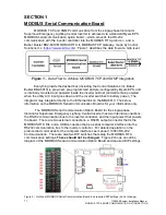
MODBUS TCP & SNMP COMMUNICATION OPTION SECTION
Babel Buster BB2-6010
The Babel Buster BB2-6010 is a DIN-rail mounted protocol bridge that is
pre-programmed to convert between MODBUS RTU and MODBUS TCP and/or
SNMP. It features two external connectors; one for MODBUS RTU RS485 and
power
in (
24 Volts AC or DC), and the other for Ethernet (LAN connection)
out
.
Figure 2 is a diagram of the BB2-6010.
Figure 2
– BB2-6010 Diagram
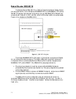
The lower (MODBUS RTU and power in) connector is pre-wired. Please
do not change the internal wiring. The upper (Ethernet) connector should be
connected to the Local Area Network (LAN) to which it will be integrated via
MODBUS TCP and/or SNMP. The BB2-6010 is preprogrammed to:
•
Provide proxy objects to read the values of the MODBUS objects
presented by the inverter (see Section 4). The proxy objects are updated
once every second.
•
Provide SNMP OIDs to access all MODBUS objects, and act as an SNMP
Agent (server) such that they can also be read via SNMP
The BB2-6010 can be configured using its onboard web server to
generate SNMP traps when programmed conditions are met (e.g.
‘inverter is
running on battery power
’, ‘inverter is overloaded’, ‘ambient temperature is too
high
’, etc.).
Содержание Illuminator Supernova Series
Страница 16: ...15 115895B System Installation Manual Figure 5 2 AC Connections for 6 25 k W 7 5 kW systems ...
Страница 17: ...16 115895B System Installation Manual Figure 5 3 AC Connections for 10 kW 16 7 kW systems ...
Страница 30: ...115895B System Installation Manual PART II OPTIONS MANUALS Section continues on next page ...
Страница 95: ...94 115895B System Installation Manual SERIAL TO ETHERNET ADAPTER OPTION SECTION ...
Страница 96: ...95 115895B System Installation Manual SERIAL TO ETHERNET ADAPTER OPTION SECTION ...
Страница 113: ...112 115895B System Installation Manual DRAWINGS SECTION PART III DRAWINGS Drawings section continues on next page ...
Страница 114: ...113 115895B System Installation Manual DRAWINGS SECTION ...
Страница 115: ...114 115895B System Installation Manual DRAWINGS SECTION ...
Страница 116: ...115 115895B System Installation Manual DRAWINGS SECTION ...
Страница 117: ...116 115895B System Installation Manual DRAWINGS SECTION ...
Страница 118: ...117 115895B System Installation Manual DRAWINGS SECTION ...
Страница 119: ...118 115895B System Installation Manual DRAWINGS SECTION ...
Страница 120: ...119 115895B System Installation Manual DRAWINGS SECTION ...
Страница 121: ...120 115895B System Installation Manual DRAWINGS SECTION ...
Страница 122: ...121 115895B System Installation Manual DRAWINGS SECTION ...
Страница 123: ...122 115895B System Installation Manual DRAWINGS SECTION ...
Страница 124: ...123 115895B System Installation Manual DRAWINGS SECTION ...
Страница 125: ...124 115895B System Installation Manual DRAWINGS SECTION ...
Страница 126: ...125 115895B System Installation Manual DRAWINGS SECTION ...
Страница 127: ...126 115895B System Installation Manual DRAWINGS SECTION ...
Страница 128: ...127 115895B System Installation Manual DRAWINGS SECTION ...
Страница 129: ...128 115895B System Installation Manual DRAWINGS SECTION ...
Страница 130: ...129 115895B System Installation Manual DRAWINGS SECTION ...
Страница 131: ...130 115895B System Installation Manual Notes ...


