


41
115895B System Installation Manual
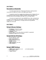
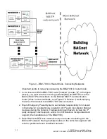
BACNET IP & SNMP COMMUNICATION OPTION SECTION
SECTION 4
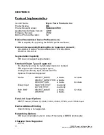
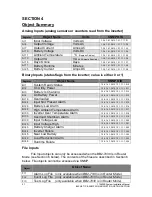
Object Summary
Analog Inputs (analog sensors or counters read from the inverter)
Register
Object Name
Units
SNMP OID
AI 1
Input Voltage
Volts AC
1.3.6.1.4.1.3815.1.3.1.1.1.1.2.1
AI 4
Output Voltage
Volts AC
1.3.6.1.4.1.3815.1.3.1.1.1.1.2.2
AI 7
Output Current
Amps AC
1.3.6.1.4.1.3815.1.3.1.1.1.1.2.3
AI 10
Battery Voltage
Volts DC
1.3.6.1.4.1.3815.1.3.1.1.1.1.2.4
AI 11
Ambient Temperature
°C
(Degrees Celsius)
1.3.6.1.4.1.3815.1.3.1.1.1.1.2.5
AI 13
Output VA
VA
(Volt-Ampere Reactive)
1.3.6.1.4.1.3815.1.3.1.1.1.1.2.6
AI 16
Days Online
Days
1.3.6.1.4.1.3815.1.3.1.1.1.1.2.7
AI 17
Battery Runtime
Minutes
1.3.6.1.4.1.3815.1.3.1.1.1.1.2.8
AI 25
Battery Current
Amps DC
1.3.6.1.4.1.3815.1.3.1.1.1.1.2.9
Binary Inputs (status flags from the inverter; value is either 0 or 1)
Register
Object Name
SNMP OID
BI 1
System Ready Status
1.3.6.1.4.1.3815.1.3.1.1.1.1.2.10
BI 2
On Utility Power
1.3.6.1.4.1.3815.1.3.1.1.1.1.2.11
BI 3
Battery Is Charging
1.3.6.1.4.1.3815.1.3.1.1.1.1.2.12
BI 4
On Battery Power
1.3.6.1.4.1.3815.1.3.1.1.1.1.2.13
BI 19
Overloaded
1.3.6.1.4.1.3815.1.3.1.1.1.1.2.14
BI 24
Input Not Present Alarm
1.3.6.1.4.1.3815.1.3.1.1.1.1.2.15
BI 26
Battery Low Alarm
1.3.6.1.4.1.3815.1.3.1.1.1.1.2.16
BI 28
High Ambient Temperature Alarm
1.3.6.1.4.1.3815.1.3.1.1.1.1.2.17
BI 30
Inverter Over Temperature Alarm
1.3.6.1.4.1.3815.1.3.1.1.1.1.2.18
BI 33
Overload Shutdown Alarm
1.3.6.1.4.1.3815.1.3.1.1.1.1.2.19
BI 39
Input Voltage Low
1.3.6.1.4.1.3815.1.3.1.1.1.1.2.20
BI 40
Input Voltage High
1.3.6.1.4.1.3815.1.3.1.1.1.1.2.21
BI 43
Battery Charger Alarm
1.3.6.1.4.1.3815.1.3.1.1.1.1.2.22
BI 44
Inverter Failure
1.3.6.1.4.1.3815.1.3.1.1.1.1.2.23
BI 45
Near Low Battery
1.3.6.1.4.1.3815.1.3.1.1.1.1.2.24
BI 46
Load Reduction Alarm
1.3.6.1.4.1.3815.1.3.1.1.1.1.2.25
BI 48
Runtime Failure
1.3.6.1.4.1.3815.1.3.1.1.1.1.2.26
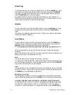
File Inputs
File Input objects can only be accessed when the BB2-7030 is in Router
Mode (see Section 6 below). The contents of the files are described in Section 6
below. File objects cannot be accessed via SNMP.
Object
Object Name
FI 1
Alarm Log File
(only available when BB2-7030 is in Router Mode)
FI 2
Event Log File
(only available when BB2-7030 is in Router Mode)
FI 3
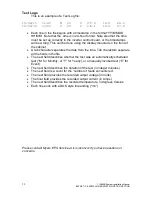
Test Log File
(only available when BB2-7030 is in Router Mode)
Содержание Illuminator Supernova Series
Страница 16: ...15 115895B System Installation Manual Figure 5 2 AC Connections for 6 25 k W 7 5 kW systems ...
Страница 17: ...16 115895B System Installation Manual Figure 5 3 AC Connections for 10 kW 16 7 kW systems ...
Страница 30: ...115895B System Installation Manual PART II OPTIONS MANUALS Section continues on next page ...
Страница 95: ...94 115895B System Installation Manual SERIAL TO ETHERNET ADAPTER OPTION SECTION ...
Страница 96: ...95 115895B System Installation Manual SERIAL TO ETHERNET ADAPTER OPTION SECTION ...
Страница 113: ...112 115895B System Installation Manual DRAWINGS SECTION PART III DRAWINGS Drawings section continues on next page ...
Страница 114: ...113 115895B System Installation Manual DRAWINGS SECTION ...
Страница 115: ...114 115895B System Installation Manual DRAWINGS SECTION ...
Страница 116: ...115 115895B System Installation Manual DRAWINGS SECTION ...
Страница 117: ...116 115895B System Installation Manual DRAWINGS SECTION ...
Страница 118: ...117 115895B System Installation Manual DRAWINGS SECTION ...
Страница 119: ...118 115895B System Installation Manual DRAWINGS SECTION ...
Страница 120: ...119 115895B System Installation Manual DRAWINGS SECTION ...
Страница 121: ...120 115895B System Installation Manual DRAWINGS SECTION ...
Страница 122: ...121 115895B System Installation Manual DRAWINGS SECTION ...
Страница 123: ...122 115895B System Installation Manual DRAWINGS SECTION ...
Страница 124: ...123 115895B System Installation Manual DRAWINGS SECTION ...
Страница 125: ...124 115895B System Installation Manual DRAWINGS SECTION ...
Страница 126: ...125 115895B System Installation Manual DRAWINGS SECTION ...
Страница 127: ...126 115895B System Installation Manual DRAWINGS SECTION ...
Страница 128: ...127 115895B System Installation Manual DRAWINGS SECTION ...
Страница 129: ...128 115895B System Installation Manual DRAWINGS SECTION ...
Страница 130: ...129 115895B System Installation Manual DRAWINGS SECTION ...
Страница 131: ...130 115895B System Installation Manual Notes ...


