


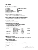


25
115895B System Installation Manual
F
RONT
P
ANEL
D
ISPLAY
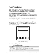
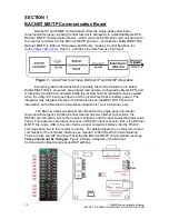
The Front Panel Display assembly consists of a 4 x 20 vacuum fluorescent
display and a 4-button keypad. The 4 buttons can navigate through all the
menus by using the left and right arrow keys, the ENTER and the ESCAPE.
The default menu will scroll between the status screen and the
Identification/Date-Time screen. To view the other menu options from the default
screen, press the
ENTER
key, and then press the left or the right arrow key to go
to the desired menu.
The
Menu’s available are Meter, Test Log, Event Log, Alarm Log, User Setup,
Factory Setup, Status, System Information, and Test Mode.
Once the desired menu has been reached, press the
ENTER
key to gain access
to this menu. Once into the menu, use the left or right arrow key to scroll to
different functions within the menu. Press the
ENTER
key again to gain access
to the desire function. To exit, press the
ESCAPE
key until the desired level has
been reached. (See figure 7.4)
Figure 7.4 Front Panel Display
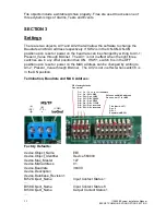
Control Panel Keypads
Table 7.1 Keypad Functions
Key Name
Description
Enter (Blue)
Pressing this key will view menus.
Escape (Black)
Pressing this key will exit out of menus and return to the
Identification/Date-Time screen.
[ ◄ ] (Red)
This key functions as Left scroll key.
[ ► ] (Red)
This key functions as Right scroll key.
Содержание Illuminator Supernova Series
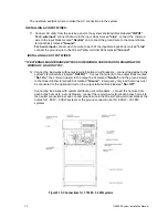
Страница 16: ...15 115895B System Installation Manual Figure 5 2 AC Connections for 6 25 k W 7 5 kW systems ...
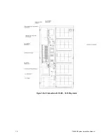
Страница 17: ...16 115895B System Installation Manual Figure 5 3 AC Connections for 10 kW 16 7 kW systems ...
Страница 30: ...115895B System Installation Manual PART II OPTIONS MANUALS Section continues on next page ...
Страница 95: ...94 115895B System Installation Manual SERIAL TO ETHERNET ADAPTER OPTION SECTION ...
Страница 96: ...95 115895B System Installation Manual SERIAL TO ETHERNET ADAPTER OPTION SECTION ...
Страница 113: ...112 115895B System Installation Manual DRAWINGS SECTION PART III DRAWINGS Drawings section continues on next page ...
Страница 114: ...113 115895B System Installation Manual DRAWINGS SECTION ...
Страница 115: ...114 115895B System Installation Manual DRAWINGS SECTION ...
Страница 116: ...115 115895B System Installation Manual DRAWINGS SECTION ...
Страница 117: ...116 115895B System Installation Manual DRAWINGS SECTION ...
Страница 118: ...117 115895B System Installation Manual DRAWINGS SECTION ...
Страница 119: ...118 115895B System Installation Manual DRAWINGS SECTION ...
Страница 120: ...119 115895B System Installation Manual DRAWINGS SECTION ...
Страница 121: ...120 115895B System Installation Manual DRAWINGS SECTION ...
Страница 122: ...121 115895B System Installation Manual DRAWINGS SECTION ...
Страница 123: ...122 115895B System Installation Manual DRAWINGS SECTION ...
Страница 124: ...123 115895B System Installation Manual DRAWINGS SECTION ...
Страница 125: ...124 115895B System Installation Manual DRAWINGS SECTION ...
Страница 126: ...125 115895B System Installation Manual DRAWINGS SECTION ...
Страница 127: ...126 115895B System Installation Manual DRAWINGS SECTION ...
Страница 128: ...127 115895B System Installation Manual DRAWINGS SECTION ...
Страница 129: ...128 115895B System Installation Manual DRAWINGS SECTION ...
Страница 130: ...129 115895B System Installation Manual DRAWINGS SECTION ...
Страница 131: ...130 115895B System Installation Manual Notes ...


