


55
115895B System Installation Manual
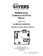
MODBUS SERIAL COMMUNICATION OPTION SECTION
SECTION 1
MODBUS Serial Comm Option Board - Introduction
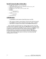
The MODBUS Communication Option Board for the single-phase
Illuminator Supernova Emergency Lighting Central Inverter has two internal
connections; the RS232 communication bus to the inverter controller, and the
input power that powers the board. There are two external connections, a
RS485 output connector that is the MODBUS link, and a USB connection that is
a serial computer interface into the RS232 communication bus to the inverter
controller. For detailed operation on the protocol and commands for the
computer interface see manual 114063 RS-232 Communications. There are
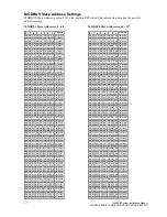
also two DIP switches that select the MODBUS protocol (RTU or ASCII), baud
rate, parity, and MODBUS slave address. See Figure 1 for the locations of these
components.
Figure 1
– Outline of MODBUS Communication Board
.
Содержание Illuminator Supernova Series
Страница 16: ...15 115895B System Installation Manual Figure 5 2 AC Connections for 6 25 k W 7 5 kW systems ...
Страница 17: ...16 115895B System Installation Manual Figure 5 3 AC Connections for 10 kW 16 7 kW systems ...
Страница 30: ...115895B System Installation Manual PART II OPTIONS MANUALS Section continues on next page ...
Страница 95: ...94 115895B System Installation Manual SERIAL TO ETHERNET ADAPTER OPTION SECTION ...
Страница 96: ...95 115895B System Installation Manual SERIAL TO ETHERNET ADAPTER OPTION SECTION ...
Страница 113: ...112 115895B System Installation Manual DRAWINGS SECTION PART III DRAWINGS Drawings section continues on next page ...
Страница 114: ...113 115895B System Installation Manual DRAWINGS SECTION ...
Страница 115: ...114 115895B System Installation Manual DRAWINGS SECTION ...
Страница 116: ...115 115895B System Installation Manual DRAWINGS SECTION ...
Страница 117: ...116 115895B System Installation Manual DRAWINGS SECTION ...
Страница 118: ...117 115895B System Installation Manual DRAWINGS SECTION ...
Страница 119: ...118 115895B System Installation Manual DRAWINGS SECTION ...
Страница 120: ...119 115895B System Installation Manual DRAWINGS SECTION ...
Страница 121: ...120 115895B System Installation Manual DRAWINGS SECTION ...
Страница 122: ...121 115895B System Installation Manual DRAWINGS SECTION ...
Страница 123: ...122 115895B System Installation Manual DRAWINGS SECTION ...
Страница 124: ...123 115895B System Installation Manual DRAWINGS SECTION ...
Страница 125: ...124 115895B System Installation Manual DRAWINGS SECTION ...
Страница 126: ...125 115895B System Installation Manual DRAWINGS SECTION ...
Страница 127: ...126 115895B System Installation Manual DRAWINGS SECTION ...
Страница 128: ...127 115895B System Installation Manual DRAWINGS SECTION ...
Страница 129: ...128 115895B System Installation Manual DRAWINGS SECTION ...
Страница 130: ...129 115895B System Installation Manual DRAWINGS SECTION ...
Страница 131: ...130 115895B System Installation Manual Notes ...


