


109
115895B System Installation Manual
BATTERY THERMAL RUNAWAY SYSTEM OPTION SECTION
Picture 3
Picture 4
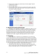
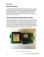
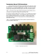
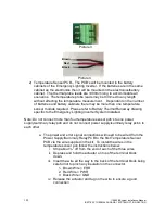
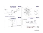
2) Temperature Sensor PCB
– The PCB’s will be mounted in the battery
cabinets of the Emergency Lighting Inverter. If the batteries are in the same
cabinet as the electronics then it will be mounted in the electronics/battery
cabinet. The thermal probe leads are 1000mm long to accommodate all
scenarios. The temperature probe leads may be trimmed to any length
without affecting the temperature measurement. Dependant on the number
of batteries and battery cabinets there may be more than one temperature
sensor module required. Please refer to Battery Thermal Runaway drawing
specific to the Emergency Lighting Inverter System Installed.
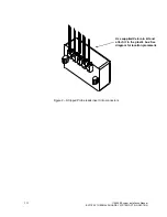
Note: Do not connect more than four
temperature sensor pcb’s to one power
supply/summary relay pcb and do not connect power suppl
y/summary relay pcb’s to
each other.
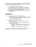
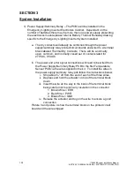
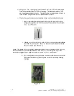
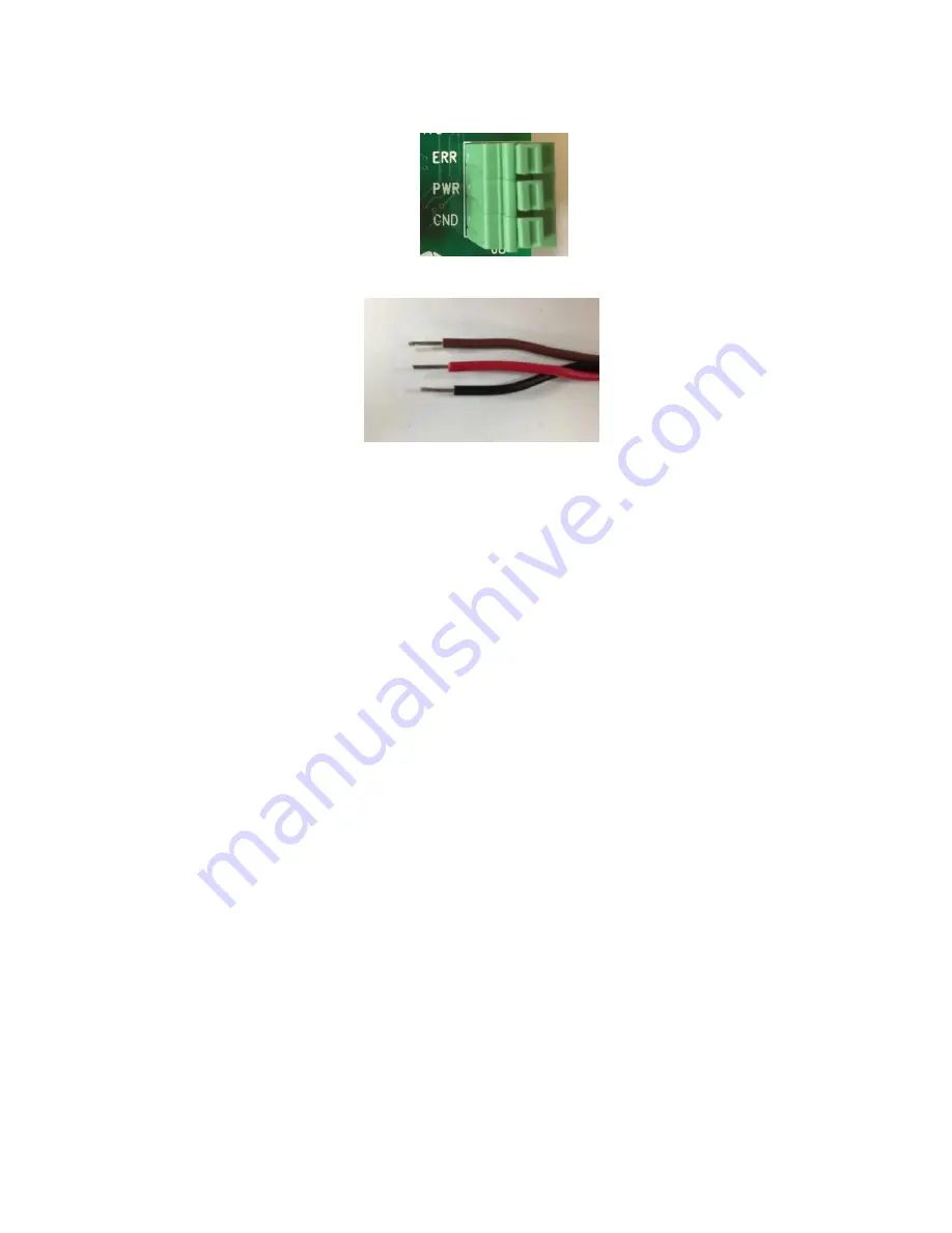
a. The power and error signal connections will need to be wired from the
Power Supply/Summary Relay PCB to the first Temperature Sensor
PCB via the wire supplied in the kit. To install the wires in the
temperature sensor pcb follow the instructions below:
i.
Strip about ¼” off from the end of each of the three wires.
ii. Depress and hold the actuator on top of the terminal block
down.
iii. Insert the wire all the way to the back of the terminal block being
careful not to pinch any insulation in the connector.
1. Brown Wire = ERR
2. Red Wire = PWR
3. Black Wire = GND
iv. Release the actuator and tug on the wire to ensure a good
connection.
Brown
Red
Black
Содержание Illuminator Supernova Series
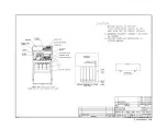
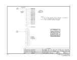
Страница 16: ...15 115895B System Installation Manual Figure 5 2 AC Connections for 6 25 k W 7 5 kW systems ...
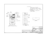
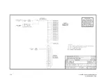
Страница 17: ...16 115895B System Installation Manual Figure 5 3 AC Connections for 10 kW 16 7 kW systems ...
Страница 30: ...115895B System Installation Manual PART II OPTIONS MANUALS Section continues on next page ...
Страница 95: ...94 115895B System Installation Manual SERIAL TO ETHERNET ADAPTER OPTION SECTION ...
Страница 96: ...95 115895B System Installation Manual SERIAL TO ETHERNET ADAPTER OPTION SECTION ...
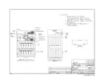
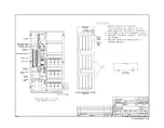
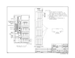
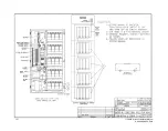
Страница 113: ...112 115895B System Installation Manual DRAWINGS SECTION PART III DRAWINGS Drawings section continues on next page ...
Страница 114: ...113 115895B System Installation Manual DRAWINGS SECTION ...
Страница 115: ...114 115895B System Installation Manual DRAWINGS SECTION ...
Страница 116: ...115 115895B System Installation Manual DRAWINGS SECTION ...
Страница 117: ...116 115895B System Installation Manual DRAWINGS SECTION ...
Страница 118: ...117 115895B System Installation Manual DRAWINGS SECTION ...
Страница 119: ...118 115895B System Installation Manual DRAWINGS SECTION ...
Страница 120: ...119 115895B System Installation Manual DRAWINGS SECTION ...
Страница 121: ...120 115895B System Installation Manual DRAWINGS SECTION ...
Страница 122: ...121 115895B System Installation Manual DRAWINGS SECTION ...
Страница 123: ...122 115895B System Installation Manual DRAWINGS SECTION ...
Страница 124: ...123 115895B System Installation Manual DRAWINGS SECTION ...
Страница 125: ...124 115895B System Installation Manual DRAWINGS SECTION ...
Страница 126: ...125 115895B System Installation Manual DRAWINGS SECTION ...
Страница 127: ...126 115895B System Installation Manual DRAWINGS SECTION ...
Страница 128: ...127 115895B System Installation Manual DRAWINGS SECTION ...
Страница 129: ...128 115895B System Installation Manual DRAWINGS SECTION ...
Страница 130: ...129 115895B System Installation Manual DRAWINGS SECTION ...
Страница 131: ...130 115895B System Installation Manual Notes ...


