Maintenance and Disassembly
Service Manual
3-25
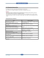
When you disassemble and reassemble
components, you must use extreme caution. The
close proximity of cables to moving parts makes
proper routing a must.
If components are removed, any cables disturbed
by the procedure must be restored as close as
possible to their original positions. Before removing
any component from the machine, note the cable
routing that will be affected.
Whenever servicing the machine, you
must perform as follows:
1. Check to verify that documents are not stored in
memory.
2. Be sure to remove the toner cartridge before you
disassemble parts.
3. Unplug the power cord.
4. Use a flat and clean surface.
5. Replace only with authorized components.
6. Do not force plastic-material components.
7. Make sure all components are in their proper
position.
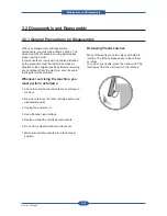
Releasing Plastic Latches
Many of the parts are held in place with plastic
latches. The latches break easily; release them
carefully.
To remove such parts, press the hook end of the
latch away from the part to which it is latched.
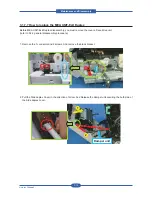
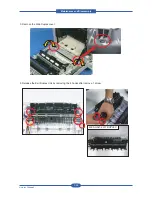
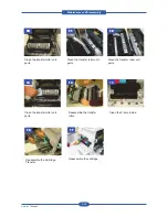
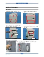
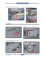
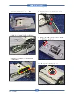
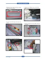
3.2 Disassembly and Reassembly
3.2.1 General Precautions on Disassembly
Содержание MFX-C4000
Страница 2: ......
Страница 14: ...Precautions Service Manual 1 6 ...
Страница 35: ...Service Manual 2 21 Video Controller Power Distribution Product Specifications and Features ...
Страница 37: ...Service Manual 2 23 Engine Controller Power Distribution Product Specifications and Features ...
Страница 39: ...Service Manual 2 25 DADF Block Diagram Product Specifications and Features ...
Страница 106: ...Maintenance and Disassembly Service Manual 3 44 ...
Страница 173: ...Alignment Troubleshooting Service Manual 4 67 Diagnostics Test Routines Other Reset Admin password ...
Страница 216: ...Alignment Troubleshooting Service Manual 4 110 ...
Страница 217: ...System Diagram Service Manual 5 1 5 System Diagram 5 1 Block Diagram 5 1 1 System ...
Страница 218: ...System Diagram Service Manual 5 2 5 1 2 Video Controller ...
Страница 219: ...System Diagram Service Manual 5 3 5 1 3 Engin Controller ...
Страница 220: ...System Diagram Service Manual 5 4 5 1 4 OPE Unit ...
Страница 221: ...System Diagram Service Manual 5 5 5 1 5 DADF ...
Страница 222: ...System Diagram Service Manual 5 6 5 1 6 SCF HCF ...
Страница 225: ...System Diagram Service Manual 5 9 5 2 3 OPE Unit ...
Страница 226: ...System Diagram Service Manual 5 10 5 2 4 DADF ...
Страница 227: ...System Diagram Service Manual 5 11 5 2 5 SCF HCF ...
Страница 228: ...System Diagram Service Manual 5 12 ...
Страница 237: ...Reference Information Service Manual 6 9 ...
Страница 238: ...Reference Information Service Manual 6 10 ...
Страница 239: ...Reference Information Service Manual 6 11 ...
Страница 240: ...Reference Information Service Manual 6 12 ...
Страница 273: ...Installation Service Manual 7 31 5 Connect the foreign device interface harness to video controller ...
Страница 279: ......
Страница 280: ...Muratec America Inc 3301 East Plano Parkway Ste 100 Plano Texas 75074 469 429 3300 Tel 469 429 3465 Fax www muratec com ...

