Service Manual
2-30
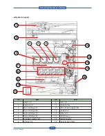
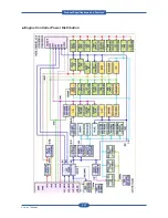
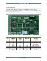
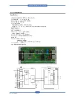
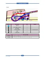
Saw-plate (to T2 Unit)
Fuser-bias (to Fuser)
DEVE_Y/M/C/K (to Drum-cartridge)
HVPS_L/S_ connection (from HVPS_L)
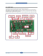
HVPS_S (High Voltage Power Supply_Small) supplies High Voltage power to Drum-cartridge (Developer),
Fuser, Saw-plate (T2-Unit).
• Specification
Channel
AC/DC No.
Type
Control
Rated
Load
Output
Output
Range
Load
Range
MHV
DC-
4
Constant-V
PWM Duty
250 pF
-700 V
0 ~ -1800 V
0.1~3 mA
AC
-
PWM Duty
1.6 KVpp
1.0 ~ 3.2 Vpp
DEVE
DC-
4
Constant-V
PWM Duty
400 MΩ
-500 V
0 ~ -800 V
0 ~ 30 uA
T1
DC+
4
Constant-I
PWM Duty
90 MΩ
14 uA
0 ~ 40 uA
0 ~ 3.5 KV
T2
DC+
1
Constant-I
PWM Duty
100 MΩ
30 uA
0 ~ 50 uA
0 ~ 6.5 KV
DC-
Constant-V
Volume
80 MΩ
-1300 V
-
0 ~ 20 uA
Saw Plate
DC-
1
Constant-V
PWM Duty
NO
-1000 V
0 ~ -2.4 KV
0 ~ 40 uA
Fuser Bias
DC+
1
Constant-V
PWM Duty
NO
1000 V
0 ~ 1.5 KV
0 ~ 20 uA
• Constant current outputs in T1/T2 channels.
• Individual T1 channels for each color.
• Alternative DC +/- outputs between image & non-image periods in T2.
• AC + DC MHV Bias.
• Rated loads in all channels could be change according to the environmental conditions.
• All output channels can be adjusted by using volume control components.
Product
S
pec
ifications
and
F
eature
s
Содержание MFX-C4000
Страница 2: ......
Страница 14: ...Precautions Service Manual 1 6 ...
Страница 35: ...Service Manual 2 21 Video Controller Power Distribution Product Specifications and Features ...
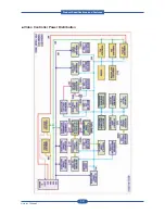
Страница 37: ...Service Manual 2 23 Engine Controller Power Distribution Product Specifications and Features ...
Страница 39: ...Service Manual 2 25 DADF Block Diagram Product Specifications and Features ...
Страница 106: ...Maintenance and Disassembly Service Manual 3 44 ...
Страница 173: ...Alignment Troubleshooting Service Manual 4 67 Diagnostics Test Routines Other Reset Admin password ...
Страница 216: ...Alignment Troubleshooting Service Manual 4 110 ...
Страница 217: ...System Diagram Service Manual 5 1 5 System Diagram 5 1 Block Diagram 5 1 1 System ...
Страница 218: ...System Diagram Service Manual 5 2 5 1 2 Video Controller ...
Страница 219: ...System Diagram Service Manual 5 3 5 1 3 Engin Controller ...
Страница 220: ...System Diagram Service Manual 5 4 5 1 4 OPE Unit ...
Страница 221: ...System Diagram Service Manual 5 5 5 1 5 DADF ...
Страница 222: ...System Diagram Service Manual 5 6 5 1 6 SCF HCF ...
Страница 225: ...System Diagram Service Manual 5 9 5 2 3 OPE Unit ...
Страница 226: ...System Diagram Service Manual 5 10 5 2 4 DADF ...
Страница 227: ...System Diagram Service Manual 5 11 5 2 5 SCF HCF ...
Страница 228: ...System Diagram Service Manual 5 12 ...
Страница 237: ...Reference Information Service Manual 6 9 ...
Страница 238: ...Reference Information Service Manual 6 10 ...
Страница 239: ...Reference Information Service Manual 6 11 ...
Страница 240: ...Reference Information Service Manual 6 12 ...
Страница 273: ...Installation Service Manual 7 31 5 Connect the foreign device interface harness to video controller ...
Страница 279: ......
Страница 280: ...Muratec America Inc 3301 East Plano Parkway Ste 100 Plano Texas 75074 469 429 3300 Tel 469 429 3465 Fax www muratec com ...


