Reference Information
Service Manual
6-4
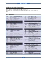
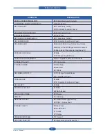
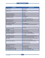
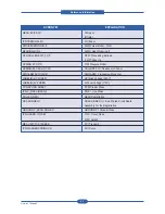
ELA HOU-SCANNER ASS’Y
ELA=Electrical Assembly, HOU =Housing
MEA UNIT-COVER PA EXIT ASS’Y
MEA= Mechanical Assembly, PA=Paper
PMO-TRAY EXTENTION MP NE
PMO= Processing Mold
MP=Multi-Purpose(Bypass) tray
NE=for NEC
MEC-CASSETTE ASS’Y(LETTER)
MEC = Mechanic Combined unit
COVER-M-FRONT
M=Mold
MPR-NAME/PLATE
MPR= Machinery Press,
UNIT-LSU
LSU =Laser Scanning Unit
SMPS-SMPS(V1)+HVPS
SMPS =Switching Mode Power Supply
HVPS =High Voltage Power Supply
ELA-OPC UNIT SET
OPC=Organic Photo-Conductive
ELA HOU-MP ASS’Y
MP =Multi-Purpose (Bypass) tray
PBA MAIN-MAIN
PBA =Printed circuit Board Assembly
PMO-CONNECT PAPER MFP
MFP =Multi-Functional Peripheral
FAN-DC
DC =Direct Current
CBF POWER STITCH GRAY
CBF= Cable Form
MEA UNIT GUIDE CST PA ASS’Y
CST=Cassette(Paper tray), PA=Paper
PBA LIU
PBA =Printed circuit Board Assembly
LIU =Line Interface Unit for FAX
SHIELD-P_MAIN LOWER
P=Press
CBF HARNESS-LIU GND
LIU =Line Interface Unit for FAX
GND= Ground
PMO-COVER FEED AY
AY=Assembly
PMO-COVER BRKT MOTER
BRKT=Bracket
CBF HARNESS-LSU
LSU =Laser Scanning Unit
IPR-SHIELD SMPS UPPERI
IPR=Iron Press
PMO-BUSHING P/U.MP
P/U=Pickup
MP=Multi-Purpose (Bypass) Tray
PMO-HOLDER GEAR TRr
TR= Transfer Roller
SPRING ETC-TR_L
TR_L=Transfer Roller - Left
PMO-CAM JAM REMOVE
PMO-CAM= Processing Mold-CAM
PMO-LOCKER DEVE
DEVE=Developer
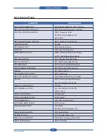
6.2.2 Service Parts
ACRONYM
EXPLANATION
Содержание MFX-C4000
Страница 2: ......
Страница 14: ...Precautions Service Manual 1 6 ...
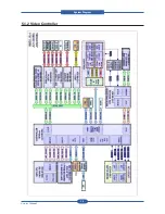
Страница 35: ...Service Manual 2 21 Video Controller Power Distribution Product Specifications and Features ...
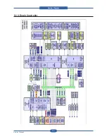
Страница 37: ...Service Manual 2 23 Engine Controller Power Distribution Product Specifications and Features ...
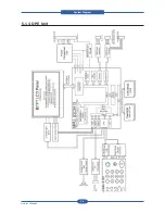
Страница 39: ...Service Manual 2 25 DADF Block Diagram Product Specifications and Features ...
Страница 106: ...Maintenance and Disassembly Service Manual 3 44 ...
Страница 173: ...Alignment Troubleshooting Service Manual 4 67 Diagnostics Test Routines Other Reset Admin password ...
Страница 216: ...Alignment Troubleshooting Service Manual 4 110 ...
Страница 217: ...System Diagram Service Manual 5 1 5 System Diagram 5 1 Block Diagram 5 1 1 System ...
Страница 218: ...System Diagram Service Manual 5 2 5 1 2 Video Controller ...
Страница 219: ...System Diagram Service Manual 5 3 5 1 3 Engin Controller ...
Страница 220: ...System Diagram Service Manual 5 4 5 1 4 OPE Unit ...
Страница 221: ...System Diagram Service Manual 5 5 5 1 5 DADF ...
Страница 222: ...System Diagram Service Manual 5 6 5 1 6 SCF HCF ...
Страница 225: ...System Diagram Service Manual 5 9 5 2 3 OPE Unit ...
Страница 226: ...System Diagram Service Manual 5 10 5 2 4 DADF ...
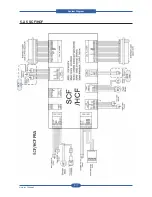
Страница 227: ...System Diagram Service Manual 5 11 5 2 5 SCF HCF ...
Страница 228: ...System Diagram Service Manual 5 12 ...
Страница 237: ...Reference Information Service Manual 6 9 ...
Страница 238: ...Reference Information Service Manual 6 10 ...
Страница 239: ...Reference Information Service Manual 6 11 ...
Страница 240: ...Reference Information Service Manual 6 12 ...
Страница 273: ...Installation Service Manual 7 31 5 Connect the foreign device interface harness to video controller ...
Страница 279: ......
Страница 280: ...Muratec America Inc 3301 East Plano Parkway Ste 100 Plano Texas 75074 469 429 3300 Tel 469 429 3465 Fax www muratec com ...

