


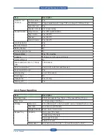

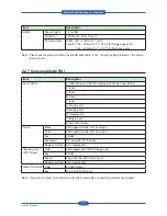
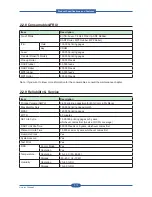


Precautions
Service Manual
1-5
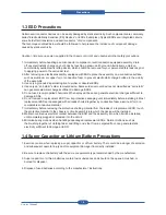
1.3 ESD Precautions
Certain semiconductor devices can be easily damaged by static electricity. Such components are commonly
called “Electrostatically Sensitive (ES) Devices” or ESDs. Examples of typical ESDs are: integrated circuits,
some field effect transistors, and semiconductor “chip” components.
The techniques outlined below should be followed to help reduce the incidence of component damage
caused by static electricity.
Caution >>Be sure no power is applied to the chassis or circuit, and observe all other safety precautions.
1. Immediately before handling a semiconductor component or semiconductor-equipped assembly, drain
off any electrostatic charge on your body by touching a known earth ground. Alternatively, employ a
commercially available wrist strap device, which should be removed for your personal safety reasons prior
to applying power to the unit under test.
2. After removing an electrical assembly equipped with ESDs, place the assembly on a conductive surface,
such as aluminum or copper foil, or conductive foam, to prevent electrostatic charge buildup in the vicinity
of the assembly.
3. Use only a grounded tip soldering iron to solder or desolder ESDs.
4. Use only an “anti-static” solder removal device. Some solder removal devices not classified as “anti-static”
can generate electrical charges sufficient to damage ESDs.
5. Do not use Freon-propelled chemicals. When sprayed, these can generate electrical charges sufficient to
damage ESDs.
6. Do not remove a replacement ESD from its protective packaging until immediately before installing it. Most
replacement ESDs are packaged with all leads shorted together by conductive foam, aluminum foil, or a
comparable conductive material.
7. Immediately before removing the protective shorting material from the leads of a replacement ESD, touch
the protective material to the chassis or circuit assembly into which the device will be installed.
8. Maintain continuous electrical contact between the ESD and the assembly into which it will be installed,
until completely plugged or soldered into the circuit.
9. Minimize bodily motions when handling unpackaged replacement ESDs. Normal motions, such as
the brushing together of clothing fabric and lifting one’s foot from a carpeted floor, can generate static
electricity sufficient to damage an ESD.
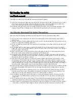
1.4 Super Capacitor or Lithium Battery Precautions
1. Exercise caution when replacing a super capacitor or Lithium battery. There could be a danger of explosion
and subsequent operator injury and/or equipment damage if incorrectly installed.
2. Be sure to replace the battery with the same or equivalent type recommended by the manufacturer.
3. Super capacitor or Lithium batteries contain toxic substances and should not be opened, crushed, or
burned for disposal.
4. Dispose of used batteries according to the manufacture? instructions.
Содержание MFX-C4000
Страница 2: ......
Страница 14: ...Precautions Service Manual 1 6 ...
Страница 35: ...Service Manual 2 21 Video Controller Power Distribution Product Specifications and Features ...
Страница 37: ...Service Manual 2 23 Engine Controller Power Distribution Product Specifications and Features ...
Страница 39: ...Service Manual 2 25 DADF Block Diagram Product Specifications and Features ...
Страница 106: ...Maintenance and Disassembly Service Manual 3 44 ...
Страница 173: ...Alignment Troubleshooting Service Manual 4 67 Diagnostics Test Routines Other Reset Admin password ...
Страница 216: ...Alignment Troubleshooting Service Manual 4 110 ...
Страница 217: ...System Diagram Service Manual 5 1 5 System Diagram 5 1 Block Diagram 5 1 1 System ...
Страница 218: ...System Diagram Service Manual 5 2 5 1 2 Video Controller ...
Страница 219: ...System Diagram Service Manual 5 3 5 1 3 Engin Controller ...
Страница 220: ...System Diagram Service Manual 5 4 5 1 4 OPE Unit ...
Страница 221: ...System Diagram Service Manual 5 5 5 1 5 DADF ...
Страница 222: ...System Diagram Service Manual 5 6 5 1 6 SCF HCF ...
Страница 225: ...System Diagram Service Manual 5 9 5 2 3 OPE Unit ...
Страница 226: ...System Diagram Service Manual 5 10 5 2 4 DADF ...
Страница 227: ...System Diagram Service Manual 5 11 5 2 5 SCF HCF ...
Страница 228: ...System Diagram Service Manual 5 12 ...
Страница 237: ...Reference Information Service Manual 6 9 ...
Страница 238: ...Reference Information Service Manual 6 10 ...
Страница 239: ...Reference Information Service Manual 6 11 ...
Страница 240: ...Reference Information Service Manual 6 12 ...
Страница 273: ...Installation Service Manual 7 31 5 Connect the foreign device interface harness to video controller ...
Страница 279: ......
Страница 280: ...Muratec America Inc 3301 East Plano Parkway Ste 100 Plano Texas 75074 469 429 3300 Tel 469 429 3465 Fax www muratec com ...