Alignment & Troubleshooting
Service Manual
4-81
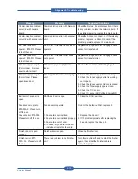
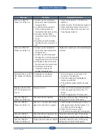
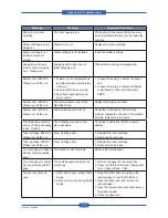
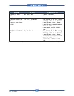
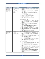
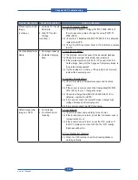
Problem Description
Cause Description
Action to Resolve
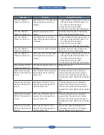
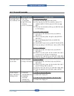
Horizontal Thick
Band(s) for a
Particular Color
(continue..)
1. Unstable Charging
Bias
2. Unstable Transfer
Bias
(continue..)
1.3) If the ITB grounding is OK, check the THV bias. [TM #107-
0000~0009]
- If there is any wrong value, change the value [TM #107-
0000~0009],
- If the THV value is defective [EDC #107-0000~0005],
replace the HVPS.
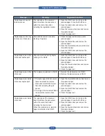
1.4) Check the Transfer Bias Harness.
1.5) If it is OK, check the Charging Bias Harness.
1.6) If it is OK, replace the Imaging unit.
1.7) If the problem persists, replace the HVPS.
[2. Unstable Transfer Bias]
2.1) Check and confirm the transfer bias [TM #107-0000~0009].
If there is any wrong value, change the value [TM #107-
0000~0009].
2.2) If the THV value is defective [EDC #107-0000~0005],
replace the HVPS.
2.3) Check the transfer bias noise [EDC #107-0000~0005].
If there is a noise, check the ITB grounding.
2.4) If the grounding is OK, check the transfer bias connection.
2.5) If the transfer bias harness is connected properly, replace
the ITB.
2.6) If the problem persists, replace the HVPS
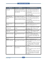
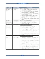
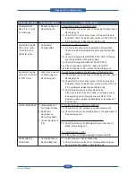
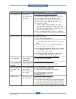
Horizontal Dark
Band on Black
Image
1. High Transfer
Voltage
2. Low Image Density
[1. High Transfer Voltage]
1.1) Check and confirm the THV bias[TM #107-0000~0009].
If there is any wrong value, change the value [TM #107-
0000~0009].
1.2) If the THV value is defective [EDC #107-0000~0005], check
the T1 roller contact conditions.
1.3) Check the T1 Bias Harness.
1.4) Check the ITB grounding. If it is defective, replace the ITB.
1.5) If the problem persists, replace the HVPS
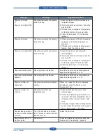
[2. Low Image Density]
2.1) Check the T/C control value [TM #111-0006~0017]. If there
is any wrong value, change the value.
2.2) Check that the density is increasing or not. [EDC #117-
0000]
2.3) If the density is not increasing, check the CTD density [EDC
#117-0001]. And increase the color density until proper
level on Custom Color Setting.
2.4) If you can't increase the density on Custom Color, change
the T/C control value to increae the density [TM #111-
0006~0017].
Содержание MFX-C4000
Страница 2: ......
Страница 14: ...Precautions Service Manual 1 6 ...
Страница 35: ...Service Manual 2 21 Video Controller Power Distribution Product Specifications and Features ...
Страница 37: ...Service Manual 2 23 Engine Controller Power Distribution Product Specifications and Features ...
Страница 39: ...Service Manual 2 25 DADF Block Diagram Product Specifications and Features ...
Страница 106: ...Maintenance and Disassembly Service Manual 3 44 ...
Страница 173: ...Alignment Troubleshooting Service Manual 4 67 Diagnostics Test Routines Other Reset Admin password ...
Страница 216: ...Alignment Troubleshooting Service Manual 4 110 ...
Страница 217: ...System Diagram Service Manual 5 1 5 System Diagram 5 1 Block Diagram 5 1 1 System ...
Страница 218: ...System Diagram Service Manual 5 2 5 1 2 Video Controller ...
Страница 219: ...System Diagram Service Manual 5 3 5 1 3 Engin Controller ...
Страница 220: ...System Diagram Service Manual 5 4 5 1 4 OPE Unit ...
Страница 221: ...System Diagram Service Manual 5 5 5 1 5 DADF ...
Страница 222: ...System Diagram Service Manual 5 6 5 1 6 SCF HCF ...
Страница 225: ...System Diagram Service Manual 5 9 5 2 3 OPE Unit ...
Страница 226: ...System Diagram Service Manual 5 10 5 2 4 DADF ...
Страница 227: ...System Diagram Service Manual 5 11 5 2 5 SCF HCF ...
Страница 228: ...System Diagram Service Manual 5 12 ...
Страница 237: ...Reference Information Service Manual 6 9 ...
Страница 238: ...Reference Information Service Manual 6 10 ...
Страница 239: ...Reference Information Service Manual 6 11 ...
Страница 240: ...Reference Information Service Manual 6 12 ...
Страница 273: ...Installation Service Manual 7 31 5 Connect the foreign device interface harness to video controller ...
Страница 279: ......
Страница 280: ...Muratec America Inc 3301 East Plano Parkway Ste 100 Plano Texas 75074 469 429 3300 Tel 469 429 3465 Fax www muratec com ...

