Service Manual
2-28
◆
Input / Output connector
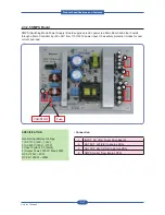
AC Input Connector( CN1 )
PIN ASSIGN
PIN NO
Description
1
AC_L
AC Input
2
AC_N
DC Output Connector( CN2 )
Description
PIN NO
PIN ASSIGN
PIN NO
Description
Power
+24V1
1
2
+24V1
Power
Power
+24V1
3
4
GND
24V Ground
24V Ground
GND
5
6
GND
24V Ground
Power
+24V2
7
8
+24V2
Power
Power
+24V2
9
10
GND
24V Ground
24V Ground
GND
11
12
GND
24V Ground
Power
+24V3
13
14
+24V3
Power
Power
+24V3
15
16
GND
24V Ground
24V Ground
GND
17
18
GND
24V Ground
Power
+24V4
19
20
+24V4
Power
Power
+24V4
21
22
GND
24V Ground
24V Ground
GND
23
24
GND
24V Ground
Signal
RS24V
25
26
reserved
Signal
(24V Remote
Sense)
(Reserved)
DC Output Connector( CN3 )
Description
PIN NO
PIN ASSIGN
PIN NO
Description
Power
+5V1
1
2
+5V1
Power
Power
+5V1
3
4
GND
5V Ground
5V Ground
GND
5
6
GND
5V Ground
Power
+5V2
7
8
+5V2
Power
Power
+5V2
9
10
GND
5V Ground
5V Ground
GND
11
12
GND
5V Ground
Power
+5V3
13
14
+5V3
Power
Power
+5V3
15
16
GND
5V Ground
5V Ground
GND
17
18
GND
5V Ground
Signal
RS5V
19
20
Standby
Signal
(5V Remote
Sense)
(Standby Mode)
Product
S
pec
ifications
and
F
eature
s
Содержание MFX-C4000
Страница 2: ......
Страница 14: ...Precautions Service Manual 1 6 ...
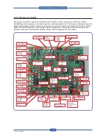
Страница 35: ...Service Manual 2 21 Video Controller Power Distribution Product Specifications and Features ...
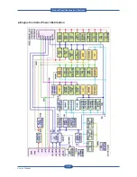
Страница 37: ...Service Manual 2 23 Engine Controller Power Distribution Product Specifications and Features ...
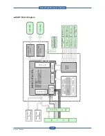
Страница 39: ...Service Manual 2 25 DADF Block Diagram Product Specifications and Features ...
Страница 106: ...Maintenance and Disassembly Service Manual 3 44 ...
Страница 173: ...Alignment Troubleshooting Service Manual 4 67 Diagnostics Test Routines Other Reset Admin password ...
Страница 216: ...Alignment Troubleshooting Service Manual 4 110 ...
Страница 217: ...System Diagram Service Manual 5 1 5 System Diagram 5 1 Block Diagram 5 1 1 System ...
Страница 218: ...System Diagram Service Manual 5 2 5 1 2 Video Controller ...
Страница 219: ...System Diagram Service Manual 5 3 5 1 3 Engin Controller ...
Страница 220: ...System Diagram Service Manual 5 4 5 1 4 OPE Unit ...
Страница 221: ...System Diagram Service Manual 5 5 5 1 5 DADF ...
Страница 222: ...System Diagram Service Manual 5 6 5 1 6 SCF HCF ...
Страница 225: ...System Diagram Service Manual 5 9 5 2 3 OPE Unit ...
Страница 226: ...System Diagram Service Manual 5 10 5 2 4 DADF ...
Страница 227: ...System Diagram Service Manual 5 11 5 2 5 SCF HCF ...
Страница 228: ...System Diagram Service Manual 5 12 ...
Страница 237: ...Reference Information Service Manual 6 9 ...
Страница 238: ...Reference Information Service Manual 6 10 ...
Страница 239: ...Reference Information Service Manual 6 11 ...
Страница 240: ...Reference Information Service Manual 6 12 ...
Страница 273: ...Installation Service Manual 7 31 5 Connect the foreign device interface harness to video controller ...
Страница 279: ......
Страница 280: ...Muratec America Inc 3301 East Plano Parkway Ste 100 Plano Texas 75074 469 429 3300 Tel 469 429 3465 Fax www muratec com ...


