


SUPREMATouch
162
Installation
MSA
US
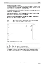
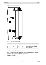
Fig. 90
System Configuration/Maximum Loads
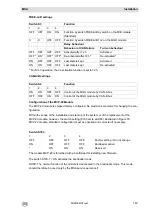
Fig. 91
MGO Module/Maximum Loads
When setting the number of modules allowable per rack, the following factors of influence have to
be observed:
-
The power of the sensors to be connected including the losses resulting from the cable lengths
(MAI module/ MIB module).
-
The currents of the modules connected to the relay driver outputs (MGO module/ MIB module:
GND terminal).
-
The power requirement of the system modules (see Fig. 148 Power Requirements of the Sys-
tem Modules).
-
The power available from the supply voltage.
For further details, see the tables in Chapter 10.11 and Chapter 14 and the operation and main-
tenance manuals of the sensors to be connected.
NOTE: A cooling fan must be installed and operated to prevent overheating in the installation
framework if more than 64 measuring points are fitted with MPI modules.
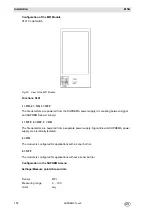
Configuration Examples
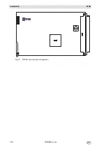
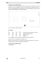
Standard System with 8 Inputs/8 Common Alarm Relays
Fig. 92
Configuration example 1
Maximum output current of an input
400 mA
Maximum output power of an input (Sensor and cable)
5 W
Maximum output power for a MAI module
40 W
Maximum output power for 8 MAI modules
320 W
Maximum input power for 8 MAI module
400 W
Maximum input power for a MIB module (for a track)
480 W
Maximum current load for a MIB module
20A
Maximum current load MIB module/GND terminal
(MAI module and MGO module current)
32A
Maximum output current for a MSP module (Rack - power pack)
6.5 A
Maximum output power for a MSP module (Rack - power pack)
150 W
Normal current of a driver output
0.3 A
Maximum current of a driver output
1.0 A
Maximum current for 8 driver outputs
(a MGO module has each 5 driver ICs with each 8 driver outputs)
4.0 A (8 x 0.5 A)
Maximum current total of all currents loads of a MGO module (one MGO
module is disposing of 40 driver outputs)
12 A (40 x 0.3 A)
Содержание SUPREMA Touch
Страница 2: ...Manual SUPREMATouch Fire and Gas Warning Unit Order No 10126972 00...
Страница 7: ...SUPREMATouch 6 Contents MSA US...
Страница 8: ...User Instruction Manual SUPREMATouch Fire and Gas Warning Unit...
Страница 104: ...Service and Maintenance Guide SUPREMATouch Fire and Gas Warning Unit...
Страница 112: ...Installation and Start Up Manual SUPREMATouch Fire and Gas Warning Unit...
Страница 151: ...SUPREMATouch 150 Installation MSA US Fig 79 MCP Module standard configuration...
Страница 303: ...SUPREMA 302 Dimensions MSA GB 16 Dimensions 16 1 Rack...
Страница 304: ...MSA AUER MSA Dimensions SUPREMA 303 GB 16 2 Rail mounted Modules MRO 8 TS Module MRO 16 TS Module...
Страница 306: ...MSA AUER MSA Dimensions SUPREMA 305 GB MRO20 8 TS Module 1 3 2 69 90...
Страница 307: ...SUPREMA 306 Dimensions MSA GB MRO20 16 TS Module 2 5 2 64 73 relay dependent 90...
Страница 308: ...MSA AUER MSA Dimensions SUPREMA 307 GB MRC TS Module MGT 40 TS Module...
Страница 309: ...SUPREMA 308 Dimensions MSA GB MHD TS Module MAT TS Module...