


MSA AUER
MSA
Installation
SUPREMATouch
165
US
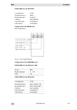
MST Module G Status A:
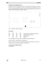
Connection of 2 racks:
Fig. 96
The CAN terminating resistor at Rack 1 is not set, at Rack 2 it is set.
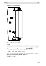
Connection of 3 racks:
Fig. 97
The CAN terminating resistor at Rack 1 and Rack 2 is not set, at Rack 3 it is set.
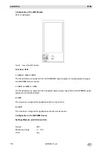
Connection of 4 racks:
Fig. 98
The CAN terminating resistor at Rack 1, Rack 2 and Rack 3 is not set, at Rack 4 it is set.
For every further rack, a T-piece, ribbon cable and a CAN line socket/plug is needed.
Содержание SUPREMA Touch
Страница 2: ...Manual SUPREMATouch Fire and Gas Warning Unit Order No 10126972 00...
Страница 7: ...SUPREMATouch 6 Contents MSA US...
Страница 8: ...User Instruction Manual SUPREMATouch Fire and Gas Warning Unit...
Страница 104: ...Service and Maintenance Guide SUPREMATouch Fire and Gas Warning Unit...
Страница 112: ...Installation and Start Up Manual SUPREMATouch Fire and Gas Warning Unit...
Страница 151: ...SUPREMATouch 150 Installation MSA US Fig 79 MCP Module standard configuration...
Страница 303: ...SUPREMA 302 Dimensions MSA GB 16 Dimensions 16 1 Rack...
Страница 304: ...MSA AUER MSA Dimensions SUPREMA 303 GB 16 2 Rail mounted Modules MRO 8 TS Module MRO 16 TS Module...
Страница 306: ...MSA AUER MSA Dimensions SUPREMA 305 GB MRO20 8 TS Module 1 3 2 69 90...
Страница 307: ...SUPREMA 306 Dimensions MSA GB MRO20 16 TS Module 2 5 2 64 73 relay dependent 90...
Страница 308: ...MSA AUER MSA Dimensions SUPREMA 307 GB MRC TS Module MGT 40 TS Module...
Страница 309: ...SUPREMA 308 Dimensions MSA GB MHD TS Module MAT TS Module...