


SUPREMATouch
164
Installation
MSA
US
10.5 Systems Consisting of Several Racks
Systems with Central Recording of Measuring Values
In systems with several racks, which are not isolated from each other, the following points should
be kept in mind:
-
Each rack must have a guaranteed voltage supply. The GND-connectors of all racks must be
interconnected.
-
When the central unit respectively the satellites consist of several racks, note that in each rack-
group the GND-connectors must be interconnected.
-
The racks must be connected to each other by a CAN bus and the system fail relay must be
connected on each rack.
-
The racks are connected by way of the MST modules on the rear with ready-made CAN bus
cables.
-
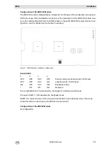
For a “multi-rack” system, contacts 1 and 2 (CAN-A, CAN-B) of the DIL switch on the MIB mod-
ule in the last rack – i.e., the one where the CAN bus ends – should be closed. All DIL switch
contacts 1 and 2 (CAN-A, CAN-B) on the racks in between must be open (Chapter 10.3).
-
The setting of the CAN bus bit rate must be the same for all racks and should correspond to
the standard settings defined for the total number of inputs in question (Chapter 10.3).
-
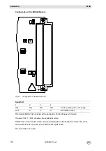
Each rack must have it own CAN node number. The standard setting for the first rack is 111
(Chapter 10.3).
-
In the case of non-redundant systems, the standard practice is to use the CAN-A bus connec-
tion; when a redundant system is built, the CAN-B is also connected (Chapter 12).
-
A cooling fan must be installed and operated for the warmth removal in the installation frame-
work if more than 64 measuring points are fitted with MPI modules.
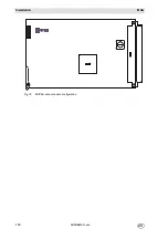
Connection Notes
The MST Module has been modified to facilitate applying the CAN Bus connections.
Unlike the previous MST module (G status A), the revised version (G status B) has an input and
output for each CAN Bus. For this reason, when connecting several racks via CAN bus, the CAN
Bus T-piece is no longer required. (Art.-No.: 10030080).
In the following, the connection of several racks (BGT) via CAN bus is described for both MST
module variations.
NOTE: For reason of clarity, only one CAN bus is described, the other CAN buses are connected
the same way.
For connections and terminal assignment see Chapter 10.10.
NOTE: The system fault relay must be wired up for all racks!
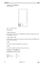
Signification:
St = Plug
B = Socket
(stands for plug connectors at the respective line)
Содержание SUPREMA Touch
Страница 2: ...Manual SUPREMATouch Fire and Gas Warning Unit Order No 10126972 00...
Страница 7: ...SUPREMATouch 6 Contents MSA US...
Страница 8: ...User Instruction Manual SUPREMATouch Fire and Gas Warning Unit...
Страница 104: ...Service and Maintenance Guide SUPREMATouch Fire and Gas Warning Unit...
Страница 112: ...Installation and Start Up Manual SUPREMATouch Fire and Gas Warning Unit...
Страница 151: ...SUPREMATouch 150 Installation MSA US Fig 79 MCP Module standard configuration...
Страница 303: ...SUPREMA 302 Dimensions MSA GB 16 Dimensions 16 1 Rack...
Страница 304: ...MSA AUER MSA Dimensions SUPREMA 303 GB 16 2 Rail mounted Modules MRO 8 TS Module MRO 16 TS Module...
Страница 306: ...MSA AUER MSA Dimensions SUPREMA 305 GB MRO20 8 TS Module 1 3 2 69 90...
Страница 307: ...SUPREMA 306 Dimensions MSA GB MRO20 16 TS Module 2 5 2 64 73 relay dependent 90...
Страница 308: ...MSA AUER MSA Dimensions SUPREMA 307 GB MRC TS Module MGT 40 TS Module...
Страница 309: ...SUPREMA 308 Dimensions MSA GB MHD TS Module MAT TS Module...