CT34002a_e.doc / Nov-15
Page 19 / 42
F02
Range
Default
F02.007 Correction Divider:
Function to provide a digital attenuation of the phase
correction signal that is produced, when the drive on
mechanical grounds (dead band or backlash) cannot respond.
In such a case, it is not desirable to make corrections
immediately. The "Correction Divider" provides a window for
the drive "backlash", within which the controller produces no
correction and a division of the differential error count.
0 = No window, Reaction to 1 increment, no division
1 = /- 1 increments, error division by 2
2 = /- 2 increments, error division by 4
3 = /- 4 increments, error division by 8
etc.
0 … 9
0
F02.008 Ramp Form:
Selects the shape of the ramps of the cutting roll speed
profile:
0: Parabolic s-ramps
(recommended in general with standard servo drives)
1: Linear ramps
(recommended with less dynamic systems, e.g. DC drives)
2: sin² shaped ramps
(recommended with extremely dynamic servo systems)
0 … 2
0
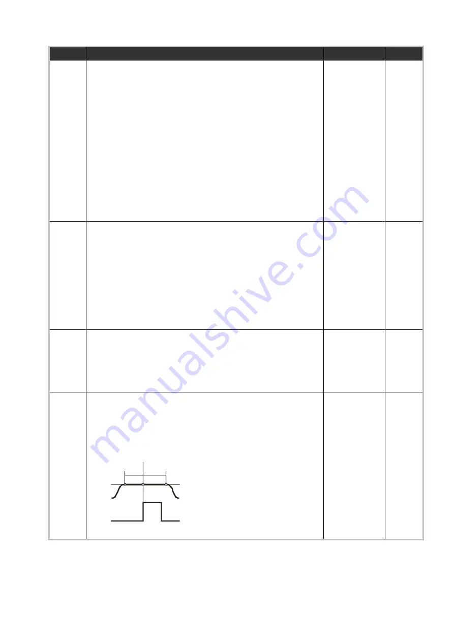
F02.009 Sync. Before Cut:
This register defines, how long before the cut (edge of the
virtual cutting pulse) the cutting roll must be synchronous to
the line.
Setting scaled in length units.
1 … 9999
10
F02.010 Sync. After Cut:
This register defines, how long after the cut (edge of the
virtual cutting pulse) the cutting roll must remain
synchronous before the speed profile starts to change speed.
Setting scaled in length units.
Sync before cut
Line speed
Sync after cut
Cutting roll speed
Cutting pulse
1 … 9999
10


