background image

AP-51xx Access Point Product Reference Guide

8-16

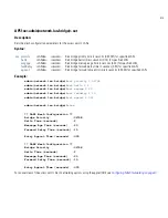
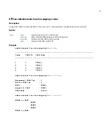
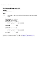
Related Commands: 

For information on configuring the LAN using the applet (GUI), see 

Configuring the LAN Interface on page 5-1

.

show 

Shows the current settings for the access point LAN port.

Содержание AP 5131 - Wireless Access Point

Страница 1: ...AP 51xx Access Point Product Reference Guide ...

Страница 2: ...Logo are registered in the US Patent Trademark Office Symbol is a registered trademark of Symbol Technologies Inc All other product or service names are the property of their respective owners 2008 Motorola Inc All rights reserved ...

Страница 3: ...AP 51xx Access Point Product Reference Guide 72E 103901 01 January 2008 ...

Страница 4: ......

Страница 5: ...formation viii Chapter 1 Introduction New Features 1 2 Adaptive AP 1 2 Rogue AP Enhancements 1 3 Bandwidth Management Enhancements 1 3 Radius Time Based Authentication 1 3 QBSS Support 1 3 Feature Overview 1 4 Single or Dual Mode Radio Options 1 5 Separate LAN and WAN Ports 1 5 Multiple Mounting Options 1 6 ...

Страница 6: ...1 12 Multiple Management Accessibility Options 1 12 Updatable Firmware 1 12 Programmable SNMP v1 v2 v3 Trap Support 1 13 Power over Ethernet Support 1 13 MU MU Transmission Disallow 1 14 Voice Prioritization 1 14 Support for CAM and PSP MUs 1 15 Statistical Displays 1 15 Transmit Power Control 1 15 Advanced Event Logging Capability 1 16 Configuration File Import Export Functionality 1 16 Default C...

Страница 7: ...t Placement 2 5 Site Surveys 2 6 Antenna Options 2 6 AP 5131 Antenna Options 2 6 AP 5181 Antenna Options 2 8 Power Options 2 9 AP 5131 Power Options 2 9 AP 5181 Power Options 2 10 Power Injector and Power Tap Systems 2 10 Installing the Power Injector or Power Tap 2 11 Preparing for Site Installation 2 11 Cabling the Power Injector and Power Tap 2 11 Power Injector LED Indicators 2 12 Mounting an ...

Страница 8: ...g WLAN Security Settings 3 12 Testing Connectivity 3 14 Where to Go from Here 3 15 Chapter 4 System Configuration Configuring System Settings 4 2 Adaptive AP Setup 4 6 Configuring Data Access 4 9 Managing Certificate Authority CA Certificates 4 14 Importing a CA Certificate 4 14 Creating Self Certificates for Accessing the VPN 4 16 Creating a Certificate for Onboard Radius Authentication 4 20 Conf...

Страница 9: ...ty of Service QoS Policy 5 39 Configuring WLAN Hotspot Support 5 45 Setting the WLAN s Radio Configuration 5 51 Configuring the 802 11a or 802 11b g Radio 5 55 Configuring Bandwidth Management Settings 5 63 Configuring Router Settings 5 66 Setting the RIP Configuration 5 67 Chapter 6 Configuring Access Point Security Configuring Security Options 6 2 Setting Passwords 6 3 Resetting the Access Point...

Страница 10: ...Radius Server 6 64 Configuring LDAP Authentication 6 67 Configuring a Proxy Radius Server 6 70 Managing the Local User Database 6 72 Mapping Users to Groups 6 74 Defining User Access Permissions by Group 6 76 Editing Group Access Permissions 6 78 Chapter 7 Monitoring Statistics Viewing WAN Statistics 7 2 Viewing LAN Statistics 7 6 Viewing a LAN s STP Statistics 7 9 Viewing Wireless Statistics 7 12...

Страница 11: ...etwork WAN Dynamic DNS Commands 8 62 Network Wireless Commands 8 66 Network WLAN Commands 8 67 Network Security Commands 8 80 Network ACL Commands 8 88 Network Radio Configuration Commands 8 93 Network Quality of Service QoS Commands 8 110 Network Bandwith Management Commands 8 115 Network Rogue AP Commands 8 118 Network MU Locationing Commands 8 128 Network Firewall Commands 8 131 Network Router ...

Страница 12: ...on 9 6 Impact of Importing Exporting Configurations to a Mesh Network 9 6 Configuring Mesh Networking Support 9 6 Setting the LAN Configuration for Mesh Networking Support 9 6 Configuring a WLAN for Mesh Networking Support 9 9 Configuring the Access Point Radio for Mesh Support 9 13 Mesh Network Deployment Quick Setup 9 20 Scenario 1 Two Base Bridges and One Client Bridge 9 20 Configuring AP 1 9 2...

Страница 13: ... 9 Topology Deployment Considerations 10 9 Extended WLANs Only 10 10 Independent WLANs Only 10 10 Extended WLANs with Independent WLANs 10 10 Extended WLAN with Mesh Networking 10 11 How the AP Receives its Adaptive Configuration 10 11 Establishing Basic Adaptive AP Connectivity 10 13 Adaptive AP Configuration 10 13 Adopting an Adaptive AP Manually 10 13 Adopting an Adaptive AP Using a Configurati...

Страница 14: ...9 Appendix B Usage Scenarios Configuring Automatic Updates using a DHCP or Linux BootP Server B 1 Windows DHCP Server Configuration B 2 Embedded Options Using Option 43 B 2 Global Options Using Extended Standard Options B 4 DHCP Priorities B 5 Linux BootP Server Configuration B 6 BootP Options B 7 BootP Priorities B 9 Configuring an IPSEC Tunnel and VPN FAQs B 9 Configuring a VPN Tunnel Between Tw...

Страница 15: ...81 model access points For the purposes of this guide the devices will be called AP 51xx or the generic term access point when identical configuration activities are applied to both models Document Conventions The following document conventions are used in this document NOTE Indicate tips or special requirements ...

Страница 16: ...contact Customer Support Refer to Appendix C for contact information Before calling have the model number and serial number at hand If the problem cannot be solved over the phone you may need to return your equipment for servicing If that is necessary you will be given specific instructions Motorola is not responsible for any damages incurred during shipment if the approved shipping container is n...

Страница 17: ...ld be aware of The AP 5181 is constructed to support outdoor installations while the AP 5131 model is constructed primarily for indoor deployments The AP 5131 is available in numerous single and dual radio SKUs while an AP 5181 is available in only a dual radio SKU An AP 5181 cannot use the AP 5131 s 48 volt power supply Part No 50 14000 243R and therefore is recommended to use the AP 5181 Power T...

Страница 18: ...iew on wireless networking fundamentals 1 1 New Features With this most recent 2 0 release of the access point firmware the following new features have been introduced Adaptive AP Rogue AP Enhancements Bandwidth Management Enhancements Radius Time Based Authentication QBSS Support Legacy users can upgrade their firmware image to version 2 0 to benefit from the new features described in this sectio...

Страница 19: ...width management can be configured uniquely for individual WLANs on different access point radios For information on configuring bandwidth management see Configuring Bandwidth Management Settings on page 5 63 1 1 4 Radius Time Based Authentication An external AAA server maintains a users and groups database used by the access point for access permissions Various kinds of access policies can be app...

Страница 20: ... carried forward from previous releases Single or Dual Mode Radio Options Separate LAN and WAN Ports Multiple Mounting Options Antenna Support for 2 4 GHz and 5 2 GHz Radios Sixteen Configurable WLANs Support for 4 BSSIDs per Radio Quality of Service QoS Support Industry Leading Data Security VLAN Support Multiple Management Accessibility Options Updatable Firmware Programmable SNMP v1 v2 v3 Trap ...

Страница 21: ...Radio Configuration on page 5 51 1 2 2 Separate LAN and WAN Ports The access point has one LAN port and one WAN port each with their own MAC address The access point must manage all data traffic over the LAN connection carefully as either a DHCP client BOOTP client DHCP server or using a static IP address The access point can only use a Power over Ethernet device when connected to the LAN port For...

Страница 22: ...e area For an overview of the Radio 1 2 4 GHz and Radio 2 5 2 GHz antennas supported on the access point s Reverse SMA RSMA connectors see Antenna Specifications on page A 5 The AP 5181 model access point uses an antenna suite primarily suited for outdoor use 1 2 5 Sixteen Configurable WLANs A Wireless Local Area Network WLAN is a data communications system that flexibly extends the functionalitie...

Страница 23: ...latency increases and throughput reductions These forms of higher priority data traffic can significantly benefit from the QoS implementation The WiFi Multimedia QOS Extensions WMM implementation used by the shortens the time between transmitting higher priority data traffic and is thus desirable for multimedia applications In addition U APSD WMM Power Save is also supported WMM defines four acces...

Страница 24: ...omputer or wireless device Authentication is critical for the security of any wireless LAN device Traditional authentication methods are not suitable for use in wireless networks where an unauthorized user can monitor network traffic and intercept passwords The use of strong authentication methods that do not disclose passwords is necessary The access point uses the Kerberos authentication service...

Страница 25: ... configuring a Radius Server for EAP 802 1x support For detailed information on EAP configurations see Configuring 802 1x EAP Authentication on page 6 11 1 2 8 3 WEP Encryption All WLAN devices face possible information theft Theft occurs when an unauthorized user eavesdrops to obtain information illegally The absence of a physical connection makes wireless links particularly vulnerable to this fo...

Страница 26: ...n Use KeyGuard to shield the master encryption keys from being discovered through hacking KeyGuard negotiation takes place between the access point and MU upon association The access point can use KeyGuard with Motorola MUs KeyGuard is only supported on Motorola MUs making it a Motorola proprietary security mechanism For detailed information on KeyGuard configurations see Configuring KeyGuard Encr...

Страница 27: ... suspicious Internet traffic from proliferating the access point managed network The access point performs network address translation NAT on packets passing to and from the WAN port This combination provides enhanced security by monitoring communication with the wired network For detailed information on configuring the access point s firewall see Configuring Firewall Settings on page 6 27 1 2 8 8...

Страница 28: ... VLAN is a group of clients with a common set of requirements independent of their physical location VLANs have the same attributes as physical LANs but they enable administrators to group clients even when they are not members of the same network segment For detailed information on configuring VLAN support see Configuring VLAN Support on page 5 5 1 2 10 Multiple Management Accessibility Options T...

Страница 29: ...int s download site contains the following 2 MIB files Symbol CC WS2000 MIB 2 0 standard MIB file Symbol AP 5131 MIB both the AP 5131 and AP 5181 use the same MIB there is no specific MIB for an AP 5181 The access point s SNMP agent functions as a command responder and is a multilingual agent responding to SNMPv1 v2c and v3 managers command generators The factory default configuration maintains SN...

Страница 30: ...re prohibits MUs from communicating with each other even if they are on different WLANs assuming one of the WLAN s is configured to disallow MU MU communication Therefore if an MU s WLAN is configured for MU MU disallow it will not be able to communicate with any other MUs connected to this access point For detailed information on configuring an WLAN to disallow MU to MU communications see Creatin...

Страница 31: ... can be displayed collectively and individually for enabled WLANs Transmit and receive statistics are available for the access point s 802 11a and 802 11b g radios An advanced radio statistics page is also available to display retry histograms for specific data packet retry information Associated MU stats can be displayed collectively and individually for specific MUs An echo ping test is also ava...

Страница 32: ...lt configuration with the exception of current WAN and SNMP settings Restoring the default configuration is a good way to create new WLANs if the MUs the access point supports have been moved to different radio coverage areas For detailed information on restoring a default or partial default configuration see Configuring System Settings on page 4 2 1 2 22 DHCP Support The access point can use Dyna...

Страница 33: ...hich accepts connections from client bridges These two modes are not mutually exclusive In client bridge mode the access point scans to find other access points using the selected WLAN s ESSID The access point must go through the association and authentication process to establish a wireless connection The mesh networking association process is identical to the access point s MU association proces...

Страница 34: ...access point now has a second LAN subnet enabling administrators to segment the access point s LAN connection into two separate networks The main access point LAN screen now allows the user to select either LAN1 or LAN2 as the active LAN over the access point s Ethernet port Both LANs can still be active at any given time but only one can transmit over the access point s physical LAN connection Ea...

Страница 35: ...tspot and wants to browse a Web page they boot their laptop and associate with a local Wi Fi network by entering a valid SSID They start a browser and the hotspot s access controller forces the un authenticated user to a Welcome page from the hotspot operator that allows the user to login with a username and password In order to send a redirected page a login page a TCP termination exists locally ...

Страница 36: ...rt about data transmission speed and duplex capabilities Auto negotiation is helpful when using the access point in an environment where different devices are connected and disconnected on a regular basis For information on configuring the auto negotiation feature see Configuring the LAN Interface on page 5 1 or Configuring WAN Settings on page 5 16 1 3 Theory of Operations To understand access po...

Страница 37: ...nagement Access Options AP 51xx MAC Address Assignment 1 3 1 Cellular Coverage An access point establishes an average communication range with MUs called a Basic Service Set BSS or cell When in a particular cell the MU associates and communicates with the access point supporting the radio coverage area of that cell Adding s to a single LAN establishes more cells to extend the range of the network ...

Страница 38: ... on its LAN and WAN interfaces and builds an address database using MAC addresses An address in the database includes the interface media that the device uses to associate with the access point The access point uses the database to forward packets from one interface to another The bridge forwards packets addressed to unknown systems to the Default Interface Ethernet The access point internal stack...

Страница 39: ...with a transmitted data stream to produce the output signal MUs receiving a direct sequence transmission use the spreading code to map the chips within the chipping sequence back into bits to recreate the original data transmitted by the access point Intercepting and decoding a direct sequence transmission requires a predefined algorithm to associate the spreading code used by the transmitting acc...

Страница 40: ...he ESSID and broadcast BSS_ID when the channel is transmission free It sends an ACK to a directed probe response from the and updates the table An MU can roam within a coverage area by switching access points Roaming occurs when Unassociated MU attempts to associate or reassociate with an available access point Supported rate changes or the MU finds a better transmit rate with another access point...

Страница 41: ...dress Translation on the Wireless interface Using NAT the router is able to manage a private IP scheme NAT allows translation of private addresses to the WAN IP address DHCP On the Wireless side the can assign private IP addresses Firewall In between the WAN and Wireless interfaces a Firewall protects against a number of known attacks 1 3 7 Management Access Options Managing the access point inclu...

Страница 42: ...6 Make configuration changes to access point s individually Optionally use the access point import export configuration function to download settings to other access points For detailed information see Importing Exporting Configurations on page 4 44 ...

Страница 43: ...not mapped to the LAN Ethernet port This address is the lowest of the two radio MAC addresses Radio1 802 11bg Random address located on the Web UI CLI and SNMP interfaces Radio2 802 11a Random address located on the Web UI CLI and SNMP interfaces The access point s BSS virtual AP MAC addresses are calculated as follows BSS1 The same as the corresponding base radio s MAC address BSS2 Base radio MAC...

Страница 44: ...AP 51xx Access Point Product Reference Guide 1 28 ...

Страница 45: ...onnection connecting antennae and applying power Installation procedures vary for different environments See the following sections for more details Precautions Requirements Access Point Placement Power Options Power Injector and Power Tap Systems Mounting an AP 5131 AP 5131 LED Indicators Mounting an AP 5181 AP 5181 LED Indicators Setting Up MUs ...

Страница 46: ...torola recommends conducting a radio site survey prior to installing an access point A site survey is an excellent method of documenting areas of radio interference and providing a tool for device placement Part No Description AP 5131 13040 WW AP 5131 802 11a g Dual Radio Access Point AP 5131 Install Guide Software and Documentation CD ROM Accessories Bag AP 5131 13041 WWR AP 5131 802 11a g Dual R...

Страница 47: ... 5131 802 11a g Single Radio Access Point AP 5131 Install Guide Software and Documentation CD ROM Accessories Bag AP 5131 40021 WWR AP 5131 802 11a g Single Radio Access Point AP 5131 Install Guide Software and Documentation CD ROM Power Injector Part No AP PSBIAS 1P2 AFR Accessories Bag AP 5131 40022 WW AP 5131 802 11a g Single Radio Access Point AP 5131 Install Guide Software and Documentation C...

Страница 48: ... Using an antenna other than the Dual Band Antenna Part No ML 2452 APA2 01 could render the AP 5131 s Rogue AP Detector Mode feature inoperable Contact your sales associate for specific information Part No Description AP 5181 13040 WWR 1 AP 5181 802 11a g Dual Radio Access Point 1 AP 5181 Install Guide 1 WEEE Regulatory Addendum 1 set of cable connectors 3 antenna dust cover 2 connector cover AP67...

Страница 49: ...logous to lighting Users might find an area lit from far away to be not bright enough An area lit sharply might minimize coverage and create dark areas Uniform antenna placement in an area like even placement of a light bulb provides even efficient coverage Place the access point using the following guidelines Install the access point at an ideal height of 10 feet from the ground Orient the access...

Страница 50: ...tennae total for dual radio models Two antennae per radio provides diversity that can improve performance and signal reception Motorola supports two antenna suites for the AP 5131 One antenna suite supporting the 2 4 GHz band and another antenna suite supporting the 5 2 GHz band Select an antenna model best suited to the intended operational environment of your AP 5131 Antenna connectors for Radio...

Страница 51: ...ctional 8 5 ML 2499 HPA3 01R Omni Directional Antenna 3 3 ML 2499 BYGA2 01R Yagi Antenna 13 9 ML 2452 APA2 01 Dual Band 3 0 NOTE An additional adapter is required to use ML 2499 11PNA2 01 and ML 2499 BYGA2 01 model antennae Please contact Motorola for more information Part No Antenna Type Nominal Net Gain dBi ML 5299 WPNA1 01R Panel Antenna 13 0 ML 5299 HPA1 01R Wide Band Omni Directional Antenna ...

Страница 52: ...dio provides diversity that can improve performance and signal reception Motorola supports two antenna suites for the AP 5181 One antenna suite supporting the 2 4 GHz band and another antenna suite supporting the 5 2 GHz band Select an antenna model best suited to the intended operational environment of your AP 5181 Refer to the following for the antenna options available to an AP 5181 model acces...

Страница 53: ...52 PNA7 01R Panel Antenna Dual Band 8 0 2 4 2 5 4 9 5 99 GHz 66 deg 60 deg Type N connector with pigtail ML 2452 PNA5 01R Sector Antenna Dual Band 6 0 2 3 2 4 4 9 5 9 GHz 120 deg Sector Type N connector with pigtail Part Number Antenna Type Nominal Net Gain dBi Description ML 5299 FHPA6 01R Omni Directional Antenna 7 0 4 900 5 850 GHz Type N connector no pigtail ML 5299 FHPA10 01R Omni Directional...

Страница 54: ...allation and allow optimal access point placement in respect to the intended radio coverage area Both the Power Injector and Power Tap are integrated AC DC converters requiring 110 220 VAC power to combine low voltage DC with Ethernet data in a single cable connecting to the access point The access point can only use a Power Injector or Power Tap when connecting the unit to the access point s LAN ...

Страница 55: ... vibration and dust The Power Injector and Power Tap are not repeaters and do not amplify the Ethernet data signal For optimal performance ensure the unit is placed as close as possible to the network data port 2 6 1 2 Cabling the Power Injector and Power Tap To install a Power Injector or Power Tap to an Ethernet data source and access point CAUTION The access point supports any standards based 8...

Страница 56: ...k and tighten the unit s LINE AC clamp by hand to ensure the power cable cannot be pulled from the unit and is protected from the elements 4 For Power Tap installations attach a ground cable between the EARTH GROUND connector on the back of the unit to a suitable earth ground connection as defined by your local electrical code 5 Verify all cable connections are complete before supplying power to t...

Страница 57: ...ons Suspended Ceiling T Bar Installations Above the Ceiling Plenum Installations 2 7 1 Desk Mounted Installations The desk mount option uses rubber feet allowing the unit to sit on most flat surfaces The four 4 round rubber feet can be found in the AP 5131 main box in a separate plastic bag To install the AP 5131 in a desk mount orientation 1 Turn the AP 5131 upside down 2 Attach the radio antenna...

Страница 58: ...r and AP 5131 does not exceed 100 meters 333 ft The Power Injector has no On Off power switch The Power Injector receives power as soon as AC power is applied For more information on using the Power Injector see Power Injector and Power Tap Systems on page 2 10 CAUTION Both the Dual and Single Radio model AP 5131 s use RSMA type antenna connectors On the Dual Radio AP 5131 a single dot on the ante...

Страница 59: ...131 system configurations see System Configuration on page 4 1 2 7 2 Wall Mounted Installations Wall mounting requires hanging the AP 5131 along its width or length using the pair of slots on the bottom of the unit and using the AP 5131 itself as a mounting template for the screws The AP 5131 can be mounted onto any plaster or wood wall surface The mounting hardware and tools customer provided req...

Страница 60: ...ut connector and the AP 5131 LAN port c Ensure the cable length from the Ethernet source host to the Power Injector and AP 5131 does not exceed 100 meters 333 ft The Power Injector has no On Off power switch The Power Injector receives power as soon as AC power is applied For more information on using the Power Injector see Power Injector and Power Tap Systems on page 2 10 CAUTION Both the Dual an...

Страница 61: ...s see System Configuration on page 4 1 2 7 3 Suspended Ceiling T Bar Installations A suspended ceiling mount requires holding the AP 5131 up against the T bar of a suspended ceiling grid and twisting the AP 5131 chassis onto the T bar The mounting hardware and tools customer provided required to install the AP 5131 on a ceiling T bar consists of Safety wire recommended Security cable optional To i...

Страница 62: ... 45 Ethernet cable between the network data supply host and the AP 5131 LAN port b Verify the power adapter is correctly rated according the country of operation c Connect the power supply line cord to the power adapter d Attach the power adapter cable into the power connector on the AP 5131 e Plug the power adapter into an outlet 5 Verify the behavior of the AP 5131 LEDs For more information see ...

Страница 63: ...he AP 5131 is ready to configure For information on an AP 5131 default configuration see Getting Started on page 3 1 For specific details on AP 5131 system configurations see System Configuration on page 4 1 CAUTION Ensure the safety wire and cabling used in the T Bar AP 5131 installation is securely fastened to the building structure in order to provide a safe operating environment NOTE If the AP...

Страница 64: ... Install a safety wire between 1 5mm 06in and 2 5mm 10in in diameter in the ceiling space 3 If required install and attach a security cable to the AP 5131 s lock port 4 Mark a point on the finished side of the tile where the light pipe is to be located 5 Create a light pipe path hole in the target position on the ceiling tile 6 Use a drill to make a hole in the tile the approximate size of the AP ...

Страница 65: ...radio antennae to their correct connectors CAUTION Motorola recommends care be taken not to damage the finished surface of the ceiling tile when creating the light pipe hole and installing the light pipe CAUTION Both the Dual and Single Radio model AP 5131s use RSMA type antenna connectors On the Dual Radio AP 5131 a single dot on the antenna connector indicates the primary antenna for both Radio ...

Страница 66: ...plied For more information on using the Power Injector see Power Injector and Power Tap Systems on page 2 10 For standard 48 Volt Power Adapter Part No 50 14000 243R and line cord installations a Connect a RJ 45 Ethernet cable between the network data supply host and the AP 5131 LAN port b Verify the power adapter is correctly rated according the country of operation c Connect the power supply lin...

Страница 67: ...tions The five AP 5131 top housing LEDs have the following display and functionality Power Status Solid white indicates the AP 5131 is adequately powered Error Conditions Solid red indicates the AP 5131 is experiencing a problem condition requiring immediate attention Ethernet Activity Flashing white indicates data transfers and Ethernet activity 802 11a Radio Activity Flickering amber indicates b...

Страница 68: ... Pole Mounted Installations AP 5181 Wall Mounted Installations 2 9 1 AP 5181 Pole Mounted Installations Complete the following steps to mount the AP 5181 to a 1 5 to 18 inch diameter steel pole or tube using the mounting bracket 1 Fit the edges of the V shaped clamp parts into the slots on the flat side of the rectangular plate 2 Place the V shaped bracket clamp parts around the pole and tighten t...

Страница 69: ...t using the provided nuts 6 Attach the radio antenna to their correct connectors NOTE The AP 5181 tilt angle may need to be adjusted during the antenna alignment process Verify the antenna polarization angle when installing ensure the antennas are oriented correctly in respect to the AP 5181 s coverage area Fit the edges of the V shaped part into the slots Tighten the securing bolts Attach the squ...

Страница 70: ...le earth ground connection as defined by your local electrical code e Ensure the cable length from the Ethernet source host to the Power Tap or Power Injector and AP 5181 does not exceed 100 meters 333 ft Neither the Power Tap or Power injector has an On Off power switch Each receives power as soon as AC power is applied For more information on using the see Power Injector and Power Tap Systems on...

Страница 71: ...d wall mounting bracket 1 Attach the bracket to a wall with flat side flush against the wall see the illustration below Position the bracket in the intended location and mark the positions of the four mounting screw holes 2 Drill four holes in the wall that match the screws and wall plugs 3 Secure the bracket to the wall 4 Attach the square mounting plate to the bridge with the supplied screws Att...

Страница 72: ...net cable between the Power Tap s DATA PWR OUT connector or the Power Injector s Data Power Out connector and the AP 5181 LAN port NOTE Once ready for the final positioning of the access point ensure the RJ45 cable connectors are oriented upwards to ensure proper operation CAUTION Do not supply power to the AP 5181 Power Tap or Power Injector until the cabling of the access point is complete CAUTI...

Страница 73: ...is applied For more information on using the see Power Injector and Power Tap Systems on page 2 10 8 Use the supplied cable connector to cover the AP 5181 s Console LAN PoE and WAN connectors 9 Once power has been applied Verify the behavior of the AP 5181 LEDs For more information see AP 5181 LED Indicators on page 2 29 The AP 5181 is ready to configure For information on an AP 5181 default confi...

Страница 74: ...diate attention Ethernet Activity Flashing white indicates data transfers and Ethernet activity 802 11a Radio Activity Flickering amber indicates beacons and data transfers over the access point 802 11a radio 802 11b g Radio Activity Flickering green indicates beacons and data transfers over the access point 802 11b g radio Power and error conditions split LED Data over Ethernet 802 11a radio acti...

Страница 75: ...dapter Users Guide available from the Motorola Web site for installing drivers and client software if operating in an 802 11a g network environment Refer to the Spectrum24 LA 4121 PC Card LA 4123 PCI Adapter LA 4137 Wireless Networker User Guide available from the Motorola Web site for installing drivers and client software if operating in an 802 11b network environment Use the default values for ...

Страница 76: ...AP 51xx Access Point Product Reference Guide 2 32 ...

Страница 77: ...options outlined in Hardware Installation See the following sections for more details Installing the Access Point Configuration Options Basic Device Configuration 3 1 Installing the Access Point Make the required cable and power connections before mounting the access point in its final operating position Test the access point with an associated MU before mounting and securing the access point Care...

Страница 78: ... AP 5131 model access point see Power Injector and Power Tap Systems on page 2 10 To verify AP 5131 LED behavior once installed see AP 5131 LED Indicators on page 2 23 To verify the behavior of the AP 5181 LEDs once installed see AP 5181 LED Indicators on page 2 29 3 2 Configuration Options Once installed and powered an AP 5131 or AP 5181 can be configured using one of several connection technique...

Страница 79: ...owing table illustrates the changes made to the access point default configuration from its initial 1 0 release through this most recent 2 0 release Version 1 0 Version 1 1 Version 1 1 1 0 1 1 2 0 Version 2 0 WAN DHCP client Auto Update Enabled Static IP 10 1 1 1 Static Mask 255 0 0 0 Static IP 10 1 1 1 Static Mask 255 0 0 0 Static IP 10 1 1 1 Static Mask 255 0 0 0 LAN1 Static IP 192 168 0 1 Stati...

Страница 80: ...t To initially connect to the access point using the access point s LAN port 1 The LAN port default is set to DHCP Connect the access point s LAN port to a DHCP server The access point will receive its IP address automatically 2 To view the IP address connect one end of a null modem serial cable to the access point and the other end to the serial port of a computer running HyperTerminal or similar...

Страница 81: ...d in this section the Java based Web UI will be used to configure the access point Use the access point s LAN interface for establishing a link with the access point Configure the access point as a DHCP client For optimal screen resolution set your screen resolution to 1024 x 768 pixels or greater 1 Log in using admin as the default Username and motorola as the default Password Use your new passwo...

Страница 82: ...s successful the Change Admin Password window displays Change the password Enter the current password and a new admin password in fields provided Click Apply Once the admin password has been updated a warning message displays stating the access point must be set to a country ...

Страница 83: ...e When you change the settings in the Quick Setup screen the values also change within the screen where these parameters also exist Additionally if the values are updated in these other screens the values initially set within the Quick Setup screen will be updated To define a basic access point configuration 1 Select System Configuration Quick Setup from the menu tree if the Quick Setup screen is ...

Страница 84: ...ountry has its own regulatory restrictions concerning electromagnetic emissions and the maximum RF signal strength that can be transmitted To ensure compliance with national and local laws be sure to set the country accurately CLI and MIB users cannot configure their access point until a two character country code for example United States us is set Refer to Appendix A Country Codes on page A 9 fo...

Страница 85: ...he Internet will be possible MUs cannot communicate beyond the configured subnets b Select the This Interface is a DHCP Client checkbox to enable DHCP for the access point s WAN connection This is useful if the larger corporate network or Internet Service Provider ISP uses DHCP DHCP is a protocol that includes mechanisms for IP address allocation and delivery of host specific configuration paramet...

Страница 86: ... the ISP b Specify the Username entered when connecting to the ISP When the Internet session begins the ISP authenticates the username c Specify the Password entered when connecting to the ISP When the Internet session starts the ISP authenticates the password For additional access point WAN port configuration options see Configuring WAN Settings on page 5 16 7 Click the LAN tab to set a minimum s...

Страница 87: ...her client To avoid this ensure all statically mapped IP addresses are outside of the IP address range assigned to the DHCP server For additional access point LAN port configuration options see Configuring the LAN Interface on page 5 1 8 Enable the radio s using the Enable checkbox es within the Radio Configuration field If using a single radio access point enable the radio then select either 2 4 ...

Страница 88: ... screen without clicking Apply results in all changes to the screens being lost 11 Click Undo Changes if necessary to undo any changes made Undo Changes reverts the settings displayed on the access point Quick Setup screen to the last saved configuration 3 5 1 1 Configuring WLAN Security Settings To configure a basic security policy for a WLAN 1 From the access point Quick Setup screen click the C...

Страница 89: ...8 Settings field as required to define the Pass Key used to generate the WEP keys Pass Key Specify a 4 to 32 character pass key and click the Generate button The access point other proprietary routers and MUs use the same algorithm to convert an ASCII string to the same hexadecimal number Non Motorola clients and devices need to enter WEP keys manually as hexadecimal numbers The access point and i...

Страница 90: ...he Key 1 4 fields to specify key numbers The key can be either a hexidecimal or ASCII depending on which option is selected from the drop down menu For WEP 64 40 bit key the keys are 10 hexadecimal characters in length or 5 ASCII characters For WEP 128 104 bit key the keys are 26 hexadecimal characters in length or 13 ASCII characters Select one of these keys for activation by clicking its radio b...

Страница 91: ...nd the users it supports Refer to the following For detailed information on access point device access SNMP settings network time importing exporting device configurations and device firmware updates see Chapter 4 System Configuration on page 4 1 For detailed information on configuring access point LAN interface subnet and WAN interface see Chapter 5 Network Management on page 5 1 For detailed inf...

Страница 92: ...AP 51xx Access Point Product Reference Guide 3 16 ...

Страница 93: ... Internet Explorer 5 0 or later or Netscape Navigator 6 0 or later To connect to the access point an IP address is required If connected to the access point using the WAN port the default static IP address is 10 1 1 1 The default password is motorola If connected to the access point using the LAN port the default setting is DHCP client The user is required to know the IP address to connect to the ...

Страница 94: ...me Protocol NTP Logging Configuration Importing Exporting Configurations Updating Device Firmware 4 1 Configuring System Settings Use the System Settings screen to specify the name and location of the access point assign an email address for the network administrator restore the AP s default configuration or restart the AP To configure System Settings for the access point 1 Select System Configura...

Страница 95: ...e the access point supports engineering retail etc System Location Enter the location of the access point The System Location parameter acts as a reminder of where the AP can be found Use the System Name field as a specific identifier of device location Use the System Name and System Location fields together to optionally define the AP name by the radio coverage it supports and specific physical l...

Страница 96: ...ware up to date For more information see Updating Device Firmware on page 4 49 System Uptime Displays the current uptime of the access point defined in the System Name field System Uptime is the cumulative time since the access point was last rebooted or lost power Serial Number Displays the access point Media Access Control MAC address The access point MAC address is hard coded at the factory and...

Страница 97: ...t the Restore Partial Default Configuration button to restore a default configuration with the exception of the current LAN WAN SNMP settings and IP address used to launch the browser If selected a message displays warning the user all current configuration settings will be lost with the exception of WAN and SNMP settings Before using this feature Motorola recommends using the Config Import Export...

Страница 98: ...ion To configure the access point s switch discovery method and connection medium 1 Select System Configuration Adaptive AP Setup from the menu tree NOTE For an AAP overview and a theoretical discussion of how an access point discovers a switch to creates a secure data tunnel for adaptive AP operation see Adaptive AP on page 10 1 NOTE AAP functionality is only supported on a Motorola WS5100 model ...

Страница 99: ... Add a complete switch fully qualified domain name FQDN to add a switch to the 12 available switch IP addresses available for connection The access point resolves the name to one or more IP addresses if a DNS IP address is present This method is used when the access point fails to obtain an IP address using DHCP PSK Before the access point sends a packet requesting its mode and configuration the s...

Страница 100: ...ndo Changes if necessary to undo any changes made Undo Changes reverts the settings displayed on the Adaptive AP Setup screen to the last saved configuration 6 Click Logout to securely exit the access point Access Point applet A prompt displays confirming the logout before the applet is closed Auto Discovery Enable When the Auto Discovery Enable checkbox is selected the access point begins the swi...

Страница 101: ...s disabled this effectively locks out the administrator from configuring the access point using that interface To avoid jeopardizing the network data managed by the access point Motorola recommends enabling only those interfaces used in the routine daily management of the network and disabling all other interfaces until they are required The AP 51XX Access screen also has a new facility allowing c...

Страница 102: ...plet using a Web browser Applet HTTPS port 443 Select the LAN1 LAN2 and or WAN checkboxes to enable access to the access point configuration applet using a Secure Sockets Layer SSL for encrypted HTTP sessions CLI TELNET port 23 Select the LAN1 LAN2 and or WAN checkboxes to enable access to the access point CLI via the TELNET terminal emulation TCP IP protocol CLI SSH port 22 Select the LAN1 LAN2 a...

Страница 103: ... authentication to occur before executing a timeout The minimum permissible value is 30 seconds SSH Keepalive Interval The SSH Keepalive Interval defines a period in seconds after which if no data has been received from a client SSH sends a message through the encrypted channel to request a response from the client The default is 0 and no messages will be sent to the client until a non zero value ...

Страница 104: ...Radius server typically listens on ports 1812 default port Shared Secret Define a shared secret for authentication on the server The shared secret is required to be the same as the shared secret defined on the Radius server Use shared secrets to verify Radius messages with the exception of the Access Request message sent by a Radius enabled device configured with the same shared secret Apply the q...

Страница 105: ... no additional message When the login message function is enabled the user can enter a 511 character maximum message describing any usage caveat required such as the authorization disclaimer displayed on the following page Thus the login message can serve an important function by discouraging unauthorized users from illegally managing the access point As your message is entered the character usage...

Страница 106: ...urely exit the access point Access Point applet A prompt displays confirming the logout before the applet is closed 4 4 Managing Certificate Authority CA Certificates Certificate management includes the following sections Importing a CA Certificate Creating Self Certificates for Accessing the VPN 4 4 1 Importing a CA Certificate A certificate authority CA is a network authority that issues and man...

Страница 107: ... a CA certificate 1 Select System Configuration Certificate Mgmt CA Certificates from the menu tree CAUTION Loaded and signed CA certificates will be lost when changing the access point s firmware version using either the GUI or CLI After a certificate has been successfully loaded export it to a secure location to ensure its availability after a firmware update If restoring the access point s fact...

Страница 108: ...the certificate ID within the View Imported root CA Certificates field to view the certificate issuer name subject and certificate expiration data 5 To delete a certificate select the Id from the drop down menu and click the Del button 4 4 2 Creating Self Certificates for Accessing the VPN The access point requires two kinds of certificates for accessing the VPN CA certificates and self certificat...

Страница 109: ...to create the certificate request The Certificate Request screen displays 3 Complete the request form with the pertinent information Only 4 values are required the others optional CAUTION Self certificates can only be generated using the access point GUI and CLI interfaces No functionality exists for creating a self certificate using the access point s SNMP configuration option ...

Страница 110: ...sh between certificates The name can be up to 7 characters in length Subject The required Subject value contains important information about the certificate Contact the CA signing the certificate to determine the content of the Subject parameter Signature Algorithm Use the drop down menu to select the signature algorithm used for the certificate Options include MD5 RSA Message Digest 5 algorithm i...

Страница 111: ...ontent of the request into the body of the message and send it to the CA The CA signs the certificate and will send it back Once received copy the content from the email into the clipboard 7 Click the Paste from clipboard button The content of the email displays in the window Click the Load Certificate button to import the certificate and make it available for use as a VPN authentication option Th...

Страница 112: ... certificate To create a self certificate for on board Radius authentication 1 Select System Configuration Certificate Mgmt Self Certificates from the access point menu tree 2 Click on the Add button to create the certificate request The Certificate Request screen displays 3 Complete the request form with the pertinent information NOTE If the access point is restarted after a certificate request h...

Страница 113: ... of the Postal Zip Code where the access point using the certificate resides Country Code Optionally enter the access point s Country Code Email Enter a organizational email address avoid using a personal address if possible to associate the request with the proper requesting organization Domain Name Ensure the Domain name is the name of the CA Server This value must be set correctly to ensure the...

Страница 114: ...in the Advanced Certificate Requests screen select the Submit a certificate request using a base 64 encoded PKCS 10 file or a renewal request using a base64 encoded PKCS file option Click Next to continue 12 Paste the content of certificate in the Saved Request field within the Submit a Saved Request screen If you do not have administrative privileges ensure the Web Server option has been selected...

Страница 115: ...MP facilitates the exchange of management information between network devices SNMP uses Management Information Bases MIBs to manage the device configuration and monitor Internet devices in potentially remote locations MIB information accessed via SNMP is defined by a set of managed objects called object identifiers OIDs An object identifier OID is used to uniquely identify each object variable of ...

Страница 116: ...ddress Mapping Symbol CC WS2000 MIB 2 0 MU ACL Configuration Symbol AP 5131 MIB VPN Tunnel Configuration Symbol CC WS2000 MIB 2 0 QOS Configuration Symbol AP 5131 MIB VPN Tunnel status Symbol CC WS2000 MIB 2 0 Radio Configuration Symbol AP 5131 MIB Content Filtering Symbol CC WS2000 MIB 2 0 Bandwidth Management Symbol AP 5131 MIB Rogue AP Detection Symbol CC WS2000 MIB 2 0 SNMP Trap Selection Symb...

Страница 117: ...ess Control sub screen Use the SNMP Access screen to define SNMP v1 v2c community definitions and SNMP v3 user definitions SNMP version 1 v1 provides a strong network management system but its security is relatively weak The improvements in SNMP version 2c v2c do not include the attempted security enhancements of other version 2 protocols Instead SNMP v2c defaults to SNMP standard community string...

Страница 118: ...s Control screen A read only community string allows a remote device to retrieve information while a read write community string allows a remote device to modify settings Motorola recommends considering adding a community definition using a site appropriate name and access level Set up a read write definition at a minimum to facilitate full access by the access point administrator 2 Configure the ...

Страница 119: ...e community Read only access allows a remote device to retrieve access point information while read write access allows a remote device to modify access point settings Add Click Add to create a new entry for an SNMP v3 user Delete Select Delete to remove an entry for an SNMP v3 user Username Specify a username by typing an alphanumeric string of up to 31 characters Security Level Use the Security ...

Страница 120: ...e same password on both pages Access Use the Access pull down list to specify read only R access or read write RW access for a user Read only access permits a user to retrieve access point information while read write access allows a user to modify access pointsettings SNMP Access Control Click the SNMP Access Control button to display the SNMP Access Control screen for specifying which users can ...

Страница 121: ...ng SNMP Access Control Use the SNMP Access Control screen as launched from the SNMP Access screen to specify which users can read SNMP generated information and if capable modify related settings from an SNMP capable client Use the SNMP Access Control screen s Access Control List ACL to limit by Internet Protocol IP address who can access the access point SNMP interface To configure SNMP user acce...

Страница 122: ... for example can use a read write community definition Use just the Starting IP Address column to specify a single SNMP user Use both the Starting IP Address and Ending IP Address columns to specify a range of addresses for SNMP users To add a single IP address to the ACL enter the same IP address in the Start IP and End IP fields Leave the ACL blank to allow access to the SNMP interface from the ...

Страница 123: ...for reporting this information Trap configuration depends on the network machine that receives the generated traps SNMP v1 v2c and v3 trap configurations function independently In a mixed SNMP environment generated traps can be sent using configurations for both SNMP v1 v2c and v3 To configure SNMP traps on the access point 1 Select System Configuration SNMP Access SNMP Trap Configuration from the...

Страница 124: ...ration entry Delete Click Delete to remove a selected SNMP v1 v2c Trap Configuration entry Destination IP Specify a numerical non DNS name destination IP address for receiving the traps sent by the access point SNMP agent Port Specify a destination User Datagram Protocol UDP port for receiving traps The default is 162 Community Enter a community name specific to the SNMP capable client that receiv...

Страница 125: ...ent receiving the traps Security Level Use the Security Level drop down menu to specify a security level of noAuth no authorization AuthNoPriv authorization without privacy or AuthPriv authorization with privacy The NoAuth setting specifies no login authorization or encryption for the user The AuthNoPriv setting requires login authorization but no encryption The AuthPriv setting requires login aut...

Страница 126: ...g Specific SNMP Traps Use the SNMP Traps screen to enable specific traps on the access point Motorola recommends defining traps to capture unauthorized devices operating within the access point coverage area Trap configuration depends on the network machine that receives the generated traps SNMP v1 v2c and v3 trap configurations function independently In a mixed SNMP environment traps can be sent ...

Страница 127: ...ated with or gets dropped from one of the access point s WLANs MU denied association Generates a trap when an MU is denied association to a access point WLAN Can be caused when the maximum number of MUs for a WLAN is exceeded or when an MU violates the access point s Access Control List ACL MU denied authentication Generates a trap when an MU is denied authentication on one of the AP s WLANs Can b...

Страница 128: ...S attack is detected by the access point firewall A new trap is sent at the specified interval until the attack has stopped Send trap every Defines the interval in seconds the access point uses to generate a trap until the Denial of Service attack is stopped Default is 10 seconds System Cold Start Generates a trap when the access point re initializes while transmitting possibly altering the SNMP a...

Страница 129: ...he SNMP RF Trap Threshold screen as a means to track RF activity and the access point s radio and associated MU performance SNMP RF Traps are sent when RF traffic exceeds defined limits set in the RF Trap Thresholds field of the SNMP RF Traps screen Thresholds are displayed for the access point WLAN selected radio and the associated MU To configure specific SNMP RF Traps on the access point 1 Sele...

Страница 130: ...e Bit Speed Enter a minimum threshold for the average bit speed in Mbps Megabits per second Average Signal Enter a minimum threshold for the average signal strength in dBm for each device Average Retries Set a maximum threshold for the average number of retries for each device Dropped Enter a maximum threshold for the total percentage of packets dropped for each device Dropped packets can be cause...

Страница 131: ...chronization is required Use the Date and Time Settings screen to enable NTP and specify the IP addresses and ports of available NTP servers To manage clock synchronization on the access point 1 Select System Configuration Date Time from the access point menu tree NOTE The current time is not set accurately when initially connecting to the access point Until a server is defined to provide the acce...

Страница 132: ...date advancing 3 Select the Set Date Time button to display the Manual Date Time Setting screen This screen enables the user to manually enter the access point s system time using a Year Month Day HH MM SS format This option is disabled when the Enable NTP checkbox has been selected and therefore should be viewed as a second means to define the access point system time 4 If using the Manual Date T...

Страница 133: ...Select the Enable NTP on access point checkbox to allow a connection between the access point and one or more specified NTP servers A preferred first alternate and second alternate NTP server cannot be defined unless this checkbox is selected Disable this option uncheck the checkbox if Kerberos is not in use and time synchronization is not necessary Preferred Time Server Specify the numerical non ...

Страница 134: ...ghput and performance of the access point or troubleshooting problems on the access point managed Local Area Network LAN Use the Logging Configuration screen to set the desired logging level standard syslog levels and view or save the current access point system log To configure event logging for the access point 1 Select System Configuration Logging Configuration from the access point menu tree 2...

Страница 135: ... access point While the AP is in operation log data temporarily resides in memory AP memory is completely cleared each time the AP reboots Logging Level Use the Logging Level drop down menu to select the desired log level for tracking system events Eight logging levels 0 to 7 are available Log Level 6 Info is the access point default log level These are the standard UNIX LINUX syslog levels The le...

Страница 136: ...ed by the imported file Therefore the imported configuration is not a merge with the configuration of the target access point The exported file can be edited with any document editor if necessary The export function will always export the encrypted Admin User password The import function will import the Admin Password only if the access point is set to factory default If the access point is not co...

Страница 137: ... motorola there will be a shared secret mis match resulting in MU authentication failures This password cannot be set using the access point Web UI and must be changed using the CLI For information on changing the shared secret password using the access point CLI see AP51xx admin network wireless security create on page 8 82 CAUTION Motorola discourages importing a 1 0 baseline configuration file ...

Страница 138: ...Server IP Enter the numerical non DNS name IP address of the destination FTP or TFTP server where the configuration file is imported or exported Filepath optional Defines the optional path name used to import export the target configuration file FTP Select the FTP radio button if using an FTP server to import or export the configuration TFTP Select the TFTP radio button if using an FTP server to i...

Страница 139: ...ation If the IP mode is set to DHCP Client IP address information is not exported true for both LAN1 LAN2 and the WAN port For LAN1 and LAN2 IP address information is only exported when the IP mode is set to either static or DHCP Server For the WAN port IP address information is only exported when the This interface is a DHCP Client checkbox is not selected For more information on these settings s...

Страница 140: ...rdware type line number 0 Import operation done 1 Export operation done 2 Import operation failed 3 Export operation failed 4 File transfer in progress 5 File transfer failed 6 File transfer done Auto cfg update Error in applying config Auto cfg update Error in getting config file Auto cfg update Aborting due to fw update failure The number value appearing at the end of some messages relates to th...

Страница 141: ... or when the access point initiates a DHCP request The firmware is automatically updated each time firmware versions are found to be different between what is running on the access point and the firmware file located on the server The configuration file is automatically updated when the configuration file name on the server is different than the name of the file previously loaded on the access poi...

Страница 142: ...rading to a new access point firmware baseline does not retain the configuration of the previous lower version firmware Motorola recommends users export their 1 0 configuration for backup purposes prior to upgrading When downloading to a lower firmware version all configuration settings are lost and the access point returns to factory default settings of the lower version For detailed update scena...

Страница 143: ...ned CA certificates will be lost when changing the access point s firmware version using either the GUI or CLI After a certificate has been successfully loaded export it to a secure location to ensure its availability after a firmware update If restoring the access point s factory default firmware you must export the certificate file BEFORE restoring the access point s factory default configuratio...

Страница 144: ... the access point Enable Automatic Firmware Update Enable Automatic Configuration Update Both DHCP options are enabled by default These options can be used to update newer firmware and configuration files on the access point For more information on how to configure a DHCP or BootP Server for the automatic upgrade process see Usage Scenarios on page B 1 The update is conducted over the LAN or WAN p...

Страница 145: ...onfiguration filenames are found to be different between the filename loaded on the access point and the configuration filename that resides on the server or when the configuration file versions are found to be different between the configuration file version loaded on the access point and the configuration file that resides on server A configuration update will only occur if the access point is r...

Страница 146: ...pdate the AP reboots and completes the update 10 After the AP reboots return to the Firmware Update screen Check the Status field to verify whether the firmware update was successful If an error occurs one of the following error messages will display FAIL auto fw update check FAIL network activity time out FAIL firmware check FAIL exceed memory limit FAIL authentication FAIL connection time out FA...

Страница 147: ...wngrading access point configurations between the 1 0 0 0 xx or 1 0 1 0 xx and 1 1 0 0 xx baselines the following should be taken into consideration as certain functionalities may not be available to the user after an upgrade downgrade When downgrading from 1 1 1 1 1 to 1 0 the access point is configured to default values After a downgrade from 1 1 1 1 0 to 1 0 x x WLANs mapped to LAN2 would still...

Страница 148: ...t in a bootloader change and the second upgrade will result in a firmware change For subsequent upgrades a single download will suffice Using Auto Update the access point will automatically update itself twice when upgrading Upgrading from v1 0 to v1 1 v1 1 1 retains existing settings Motorola recommends that users export their 1 0 configuration for backup purposes prior to upgrading When download...

Страница 149: ...he LAN Interface The access point has one physical LAN port supporting two unique LAN interfaces The access point LAN port has its own MAC address The LAN port MAC address is always the value of the access point WAN port MAC address plus 1 The LAN and WAN port MAC addresses can be located within the LAN and WAN Stats screens For information on locating the access point s MAC addresses see Viewing ...

Страница 150: ...igure the access point LAN interface 1 Select Network Configuration LAN from the access point menu tree 2 Configure the LAN Settings field to enable the access point LAN1 and or LAN2 interface assign a timeout value enable 802 1q trunking configure WLAN mapping and enable 802 1x port authentication Enable Select the LAN1 and or LAN2 checkbox to allow the forwarding of data traffic over the specifi...

Страница 151: ... on page 6 5 LAN Name Use the LAN Name field to modify the existing LAN name LAN1 and LAN2 are the default names assigned to the LANs until modified by the user Ethernet Port The Ethernet Port radio buttons allow you to select one of the two available LANs as the LAN actively transmitting over the access point s LAN port Both LANs can be active at any given time but only one can transmit over the ...

Страница 152: ...es are connected and disconnected on a regular basis Selecting Auto Negotiate disables the Mbps and duplex checkbox options 100 Mbps Select this option to establish a 100 Mbps data transfer rate for the selected half duplex or full duplex transmission over the access point s LAN port This option is not available if Auto Negotiation is selected 10 Mbps Select this option to establish a 10 Mbps data...

Страница 153: ...ften referred to as memberships for individual WLANs Both methods have their advantages and disadvantages Static VLAN membership is perhaps the most widely used method because of the relatively small administration overhead and security it provides With Static VLANs you manually assign individual WLANs to individual VLANs Although static VLANs are the most common form of VLAN assignments dynamic V...

Страница 154: ...cess point and carry traffic for all those VLANs Trunking is a function that must be enabled on both sides of a link 3 Select the VLAN Name button The VLAN name screen displays The first time the screen is launched a default VLAN name of 1 and a default VLAN ID of 1 display The VLAN name is auto generated once the user assigns a VLAN ID However the user has the option of re assigning a name to the...

Страница 155: ...AN between the locations An access point managed infrastructure could provide this connectivity but it requires VLAN numbering be managed carefully to avoid conflicts between two VLANs with the same ID 5 Define a 32 ASCII character maximum VLAN Name Enter a unique name that identifies members of the VLAN Motorola recommends selecting the name carefully as the VLAN name should signify a group of cl...

Страница 156: ... LAN1 and LAN2 A trunk port configured with 802 1Q tagging can receive both tagged and untagged traffic By default the access point forwards untagged traffic with the native VLAN configured for the port The Native VLAN is VLAN 1 by default Motorola suggests leaving the Native VLAN set to 1 as other layer 2 devices also have their Native VLAN set to 1 10 Use the LAN drop down menu to map one of the...

Страница 157: ...rting the sales area then WLAN1 should be mapped to sales if a sales VLAN has been already been created 13 Click Apply to return to the VLAN Name screen Click OK to return to the LAN screen Once at the LAN screen click Apply to re apply your changes 5 1 2 Configuring LAN1 and LAN2 Settings Both LAN1 and LAN2 have separate sub screens to configure the DHCP settings used by the LAN1 and LAN2 interfa...

Страница 158: ...ormation via this LAN1 or LAN2 connection This is recommended if the access point resides within a large corporate network or the Internet Service Provider ISP uses DHCP This setting is enabled for LAN1 by default DHCP is a protocol that includes mechanisms for IP address allocation and delivery of host specific configuration parameters from a DHCP server to a host If DHCP Client is selected the f...

Страница 159: ... the IP address range specified that IP address could still be assigned to another client To avoid this ensure all statically mapped IP addresses are outside of the IP address range assigned to the DHCP server Advanced DHCP Server Click the Advanced DHCP Server button to display a screen used for generating a list of static MAC to IP address mappings for reserved clients A separate screen exists f...

Страница 160: ...e networks in which there are more computers than available IP addresses This is useful for example in education and customer environments where MU users change frequently Use longer leases if there are fewer users Secondary DNS Server Motorola recommends entering the numerical IP address of an additional DNS server if available used if the primary DNS server goes down A maximum of two DNS servers...

Страница 161: ...ction for the length of time you specify The default interval is 86400 seconds 4 Click the Add button to create a new table entry within the Reserved Clients field If a statically mapped IP address is within the IP address range in use by the DHCP server that IP address may still be assigned to another client To avoid this ensure all statically mapped IP addresses are outside of the IP address ran...

Страница 162: ... prevents specific a potentially unneccesary frames from being processed by the access point in order to improve throughput These include certain broadcast frames from devices that consume bandwidth but are unnecessary to access point operations Use the Ethernet Type Filter Configuration screen to build a list of filter types and configure them as either allowed or denied for use with the this par...

Страница 163: ... designate whether the Ethernet Types defined for the LAN are allowed or denied for use by the access point 3 To add an Ethernet type click the Add button The Add Ethernet Type screen displays Use this screen to add one type filter option at a time for a list of up to 16 entries ...

Страница 164: ...in all changes to the screens being lost 6 Click Cancel to securely exit the LAN1 or LAN2 Ethernet Type Filter Configuration screen without saving your changes 7 Click Logout to securely exit the Access Point applet A prompt displays confirming the logout before the applet is closed 5 2 Configuring WAN Settings A Wide Area Network WAN is a widely dispersed telecommunications network The access poi...

Страница 165: ...onfigured as DHCP clients Enable WAN Interface Select the Enable WAN Interface checkbox to enable a connection between the access point and a larger network or outside world through the WAN port Disable this option to effectively isolate the access point s WAN No connections to a larger network or the Internet are possible MUs cannot communicate beyond the LAN By default the WAN port is static wit...

Страница 166: ...P address uses a series of four numbers expressed in dot notation for example 190 188 12 1 Subnet Mask Specify a subnet mask for the access point s WAN connection This number is available from the ISP for a DSL or cable modem connection or from an administrator if the access point connects to a larger network A subnet mask uses a series of four numbers expressed in dot notation similar to an IP ad...

Страница 167: ...the IP address is a numerical non DNS name Refresh Click the Refresh button to update the network address information displayed within the WAN IP Configuration field Auto Negotiation Select the Auto Negotiation checkbox to enable the access point to automatically exchange information over its WAN port about data transmission speed and duplex capabilities Auto negotiation is helpful when using the ...

Страница 168: ... currently using or deploying this protocol PPPoE is a data link protocol for dialup connections PPPoE allows a host PC to use a broadband modem DSL for access to high speed data networks Username Specify a username entered when connecting to the ISP When the Internet session begins the ISP authenticates the username Password Specify a password entered when connecting to the ISP When the Internet ...

Страница 169: ...e after outbound and inbound traffic is not detected The Idle Time field is grayed out if Keep Alive is enabled Authentication Type Use the Authentication Type menu to specify the authentication protocol s for the WAN connection Choices include None PAP or CHAP PAP or CHAP Password Authentication Protocol PAP and Challenge Handshake Authentication Protocol CHAP are competing identify verification ...

Страница 170: ... side subnets One to many mapping with a configurable range of private side IP addresses Ranges can be specified from each of the private side subnets To configure IP address mappings for the access point 1 Select Network Configuration WAN NAT from the access point menu tree 2 Configure the Address Mappings field to generate a WAN IP address define the NAT type and set outbound inbound NAT mapping...

Страница 171: ... displays the 1 to Many Mappings button in the adjacent Outbound Mappings field This button displays a screen for mapping the LAN IP addresses that are associated with each subnet Define the NAT Type as none when routable IP addresses are used on the internal network Outbound Mappings When 1 to 1 NAT is selected a single IP address can be entered in the Outbound Mappings area This address provides...

Страница 172: ...rwarding screen to modify the following Add Click Add to create a local map that includes the name transport protocol start port end port IP address and Translation Port for incoming packets Delete Click Delete to remove a selected local map entry Name Enter a name for the service being forwarded The name can be any alphanumeric string and is used for identification of the service Transport Use th...

Страница 173: ... from the access point menu tree Start Port and End Port Enter the port or ports used by the port forwarding service To specify a single port enter the port number in the Start Port area To specify a range of ports use both the Start Port and End Port options to enter the port numbers For example enter 110 in the Start Port field and 115 in the End Port field IP Address Enter the numerical non DNS...

Страница 174: ... to be updated 3 Enter the DynDNS Username for the account you wish to use for the access point 4 Enter the DynDNS Password for the account you wish to use for the access point 5 Provide the Hostname for the DynDNS account you wish to use for the access point 6 Click the Update DynDNS button to update the access point s current WAN IP address with the DynDNS service NOTE The username password and ...

Страница 175: ...ds the functionalities of a wired LAN A WLAN does not require lining up devices for line of sight transmission and are thus desirable Within the WLAN roaming users can be handed off from one access point to another like a cellular phone system WLANs can therefore be configured around the needs of specific groups of users even when they are not in physical proximity Use the access point s Wireless ...

Страница 176: ...dio designation VLAN ID and security policy of existing WLANs WLAN Name The Name field displays the name of each WLAN that has been defined The WLAN names can be modified within individual WLAN configuration screens See Creating Editing Individual WLANs on page 5 30 to change the name of a WLAN ESSID Displays the Extended Services Set Identification ESSID associated with each WLAN The ESSID can be...

Страница 177: ...rely exit the Access Point applet A prompt displays confirming the logout before the applet is closed Radio The Radio field displays the name of the access point radio the WLAN is mapped to either the 802 11a radio or the 802 11b g radio To change the radio designation for a specific WLAN see Creating Editing Individual WLANs on page 5 30 VLAN The VLAN field displays the specific VLAN the target W...

Страница 178: ...N or edit the properties of an existing WLAN 1 Select Network Configuration Wireless from the access point menu tree The Wireless Configuration screen displays 2 Click the Create button to configure a new WLAN or highlight a WLAN and click the Edit button to modify an existing WLAN Either the New WLAN or Edit WLAN screen displays NOTE Before editing the properties of an existing WLAN ensure it is ...

Страница 179: ...tion field as required for the WLAN ESSID Enter the Extended Services Set Identification ESSID associated with the WLAN The WLAN name is auto generated using the ESSID until changed by the user The maximum number of characters that can be used for the ESSID is 32 ...

Страница 180: ...each access point can only support a maximum 127 MUs spanned across its 16 available WLANs If you intend to define numerous WLANs ensure each is using a portion of the 127 available MUs and the sum of the supported MUs across all WLANs does not exceed 127 Enable Client Bridge Backhaul Select the Enable Client Bridge Backhaul checkbox to make the WLAN available in the WLAN drop down menu within the...

Страница 181: ...enu to select the security scheme best suited for the new or revised WLAN Click the Create button to jump to the New Security Policy screen where a new policy can be created to suit the needs of the WLAN For more information see Configuring WLAN Security Policies on page 5 34 MU Access Control Select an ACL policy suiting the WLAN s MU introperability requirements from the drop down menu If the ex...

Страница 182: ...it the access point s ESSID If a hacker tries to find an ESSID via an MU the ESSID does not display since the ESSID is not in the beacon Motorola recommends keeping the option enabled to reduce the likelihood of hacking into the WLAN Accept Broadcast ESSID Select the Accept Broadcast ESSID checkbox to associate an MU that has a blank ESSID regardless of which ESSID the access point is currently us...

Страница 183: ...e proximity of each other requiring the same data protection scheme To create a new security policy or modify an existing policy 1 Select Network Configuration Wireless Security from the access point menu tree The Security Configuration screen appears with existing policies and their attributes displayed NOTE When the access point is first launched a single security policy default is available and...

Страница 184: ...es using the New MU ACL Policy sub screen or edit existing policies using the Edit MU ACL Policy sub screen Once new policies are defined they are available for use within the New WLAN or Edit WLAN screens to assign to specific WLANs based on MU interoperability requirements Motorola recommends using the New MU ACL Policy or Edit MU ACL Policy screens strategically to name and configure ACL polici...

Страница 185: ... Management 5 37 2 Click the Create button to configure a new ACL policy or select a policy and click the Edit button to modify an existing ACL policy The access point supports a maximum of 16 MU ACL policies ...

Страница 186: ...obile Unit Access Control List field to allow or deny MU access to the access point The MU adoption list identifies MUs by their MAC address The MAC address is the MU s unique Media Access Control number printed on the device for example 00 09 5B 45 9B 07 by the manufacturer A maximum of 200 MU MAC addresses can be added to the New Edit MU ACL Policy screen Access for the listed Mobile Units Use t...

Страница 187: ...S policies for advanced network traffic management and multimedia applications support If the existing QoS policies are insufficient a new policy can be created or an existing policy can be modified using the New QoS Policy or Edit QoS Policy screens Once new policies are defined they are available for use within the New WLAN or Edit WLAN screens to assign to specific WLANs based on MU interoperab...

Страница 188: ...t a policy and click the Edit button to modify an existing QoS policy The access point supports a maximum of 16 QoS policies NOTE When the access point is first launched a single QoS policy default is available and mapped to WLAN 1 It is anticipated additional QoS policies will be created as the list of WLANs grows ...

Страница 189: ... products that do not support Wi Fi Multimedia WMM to provide preferred queuing for these VOIP products If the Support Voice Prioritization checkbox is selected the access point will detect non WMM capable legacy phones that connect to the access point and provide priority queueing for their traffic over normal data NOTE Wi fi functionality requires both the access point and its associated clients...

Страница 190: ...ally configure the Access Categories as setting them inappropriately could negatively impact the access point s performance 11ag wifi Use this setting for high end multimedia devices that using the high rate 802 11a or 802 11g radio 11b wifi Use this setting for high end devices multimedia devices that use the 802 11b radio 11ag default Use this setting for typical data centric MU traffic over the...

Страница 191: ...ontention window minimum value is the least amount of time the MU waits before transmitting when there is no other data traffic on the network The longer the interval the lesser likelihood of collision This value should be set to a smaller increment for higher priority traffic Reduce the value when traffic on the WLAN is anticipated as being smaller CW Max The contention window maximum value is th...

Страница 192: ... for typical data frame exchanges The access point and its associated MU activate the new U APSD power save approach when a VoIP traffic stream is detected The MU then buffers frames from the voice traffic stream and sends a VoIP frame with an implicit poll request to its associated access point The access point responds to the poll request with buffered VoIP stream frame s When a voice enabled MU...

Страница 193: ...Redirects unauthenticated users to a specific page specified by the Hotspot provider User authentication Authenticates users using a Radius server Walled garden support Enables a list of IP address not domain names accessed without authentication Billing system integration Sends accounting records to a Radius accounting server To configure hotspot functionality for an access point WLAN 1 Ensure th...

Страница 194: ...TP Redirection field to specify how the Login Welcome and Fail pages are maintained for this specific WLAN The pages can be hosted locally or remotely Use Default Files Select the Use Default Files checkbox if the login welcome and fail pages reside on the access point ...

Страница 195: ...the login welcome and fail pages To create a redirected page you need to have a TCP termination locally On receiving the user credentials from the login page the access point connects to a radius server determines the identity of the connected wireless user and allows the user to access the Internet based on successful authentication NOTE If an external URL is used the external Web pages are requi...

Страница 196: ...ddress should be entered in the White List Enable Accounting Select the Enable Accounting checkbox to enable a Radius Accounting Server used for Radius authentication for a target hotspot user Server Address Specify an IP address for the external Radius Accounting server used to provide Radius accounting for the hotspot If using this option an internal Radius server cannot be used The IP address o...

Страница 197: ...e used for the primary server Pri Server IP Define the IP address of the primary Radius server This is the address of your first choice for Radius server Pri Port Enter the TCP IP port number for the server acting as the primary Radius server The default port is 1812 Pri Secret Enter the shared secret password used with the primary Radius Server Sec Server IP Define the IP address of the secondary...

Страница 198: ...in page is designed so the submit action always posts the login data on the access point To define the White List for a target WLAN 1 Click the White List Entries button from within the WLAN s Hotspot Config screen 2 Click the Add button to define an IP address for an allowed destination IP address 3 Select a White List entry and click the Del button to remove the address from the White List 4 Cli...

Страница 199: ...ng a dual radio access point individual 802 11a and 802 11b g radios can be enabled or disabled using the Radio Configuration screen checkboxes The Radio Configuration screen displays with two tabs One tab each for the access point s radios Verify both tabs are selected and configured separately to enable the radio s and set their mesh networking definitions To set the access point radio configura...

Страница 200: ...ate If this is an existing radio within a mesh network these values update in real time 3 Select the Base Bridge checkbox to allow the access point radio to accept client bridge connections from other access points in client bridge mode The base bridge is the acceptor of mesh network data from those client bridges within the mesh network and never the initiator CAUTION If a radio is disabled be ca...

Страница 201: ...s link The default setting is WLAN1 Motorola recommends creating and naming a WLAN specifically for mesh networking support to differentiate the Mesh supported WLAN from non Mesh supported WLANs CAUTION An access point is Base Bridge mode logs out whenever a Client Bridge associates to the Base Bridge over the LAN connection This problem is not experienced over the access point s WAN connection If...

Страница 202: ...o 1 does not have a mesh connection the other radio radio 2 is not affected Radio 2 continues to beacon and associate MUs but MU s can only communicate amongst themselves using the access point Disabled is the default value Uplink Detect When Uplink Detect is selected the access point only boots up the radio configured as a client bridge The access point boots up the second radio as soon as the fi...

Страница 203: ...using the 802 11a or 802 11b g radio configuration screen described below as a sub menu item under the Radio Configuration menu item Use the radio configuration screen to set the radio s placement properties define the radio s threshold and QoS settings set the radio s channel and antenna settings and define beacon and DTIM intervals To configure the access point s 802 11a or 802 11b g radio 1 Sel...

Страница 204: ...the country of operation selected for the access point MAC Address The access point like other Ethernet devices has a unique hardware encoded Media Access Control MAC or IEEE address MAC addresses determine the device sending or receiving data A MAC address is a 48 bit number written as six hexadecimal bytes separated by colons For example 00 A0 F8 24 9A C8 For additional information on access poi...

Страница 205: ...n menu is not available if this option is not selected Automatic Selection When the access point is booted the access point scans non overlapping channels listening for beacons from other access points For 802 11b it scans channels 1 6 and 11 For 802 11a all channels are non overlapping After the channels are scanned it will select the channel with the fewest access points In the case of multiple ...

Страница 206: ...e Set Rates button to display a window for selecting minimum and maximum data transmit rates for the radio At least one Basic Rate must be selected as a minimum transmit rate value Supported Rates define the data rate the radio defaults to if a higher selected data rate cannot be maintained Click OK to implement the selected rates and return to the 802 11a or 802 11b g radio configuration screen C...

Страница 207: ...The default is 100 Avoid changing this parameter as it can adversely affect performance DTIM Interval The DTIM interval defines how often broadcast frames are delivered for each of the four access point BSSIDs If a system has an abundance of broadcast traffic and it needs to be delivered quickly Motorola recommends decreasing the DTIM interval for that specific BSSID However decreasing the DTIM in...

Страница 208: ...educed as additional access points are added If QBSS is enabled define a QBSS Beacon Interval to define the beacon time in seconds the access point uses to broadcast channel utilization information This information should be periodically accessed as the access point s network load will fluctuate throughout the day 6 Configure the Performance field to set the preamble thresholds values and QoS valu...

Страница 209: ...and TXOPs Time for each Access Category These are the QoS policies for the 802 11a or 802 11b g radio not the QoS policies configured for the WLAN as created or edited from the Quality of Service Configuration screen Motorola recommends only advanced users manually set these values If the type of data traffic is known use the drop down menu to select a 11g wifi 11b wifi 11g default 11b default 11g...

Страница 210: ...hould assign each WLAN to its own BSSID In cases where more than four WLANs are required WLANs should be grouped according to their security policies so all of the WLANs on a BSSID have the same security policy It is generally a bad idea to have WLANs with different security policies on the same BSSID as this will result in warning or error messages NOTE If using a single radio access point there ...

Страница 211: ...eeded when WLAN traffic supporting a specific network segment becomes critical Bandwidth management is configured on a per WLAN basis However with this latest version 2 0 release of access point firmware a separate tab has been created for each access point radio With this new segregated radio approach bandwidth management can be configured uniquely for individual WLANs on different access point r...

Страница 212: ...ingle WLAN can be assigned to either radio and if necessary have different bandwidth management configurations To modify a WLAN to radio assignment see Creating Editing Individual WLANs on page 5 30 3 Use the Bandwidth Share Mode drop down menu to define the order enabled WLANs receive access point services Select one of the following three options First In First Out WLANs receive services from th...

Страница 213: ...plays confirming the logout before the applet is closed Weighted Round Robin If selected a weighting prioritization scheme configured within the QoS Configuration screen is used to define which WLANs receive access point resources first WLAN Name Displays the name of the WLAN This field is read only To change the name of the WLAN see Creating Editing Individual WLANs on page 5 30 Weight This colum...

Страница 214: ...Use the access point Router screen to view the router s connected routes To access the Router screen 1 Select Network Configuration Router from the access point menu tree NOTE Though the Rogue AP and Firewall features appear after the Bandwidth Management features within the access point menu tree they are described in Chapter 6 Configuring Access Point Security on page 6 1 as both items are data ...

Страница 215: ...ng Information Protocol RIP is an interior gateway protocol that specifies how routers exchange routing table information The Router screen also allows the administrator to select the type of RIP and the type of RIP authentication used by the switch For more information on configuring RIP see Setting the RIP Configuration on page 5 67 5 Use the User Defined Routes field to add or delete static rou...

Страница 216: ... version 1 is a mature stable and widely supported protocol It is well suited for use in stub networks and in small autonomous systems that do not have enough redundant paths to warrant the overhead of a more sophisticated protocol RIP v2 v1 compat RIP version 2 compatible with version 1 is an extension of RIP v1 s capabilities but it is still compatible with RIP version 1 RIP version 2 increases ...

Страница 217: ... password of up to 15 alphanumeric characters in the Password Simple Authentication area None This option disables the RIP authentication Simple This option enable RIP version 2 s simple authentication mechanism This setting activates the Password Simple Authentication field MD5 This option enables the MD5 algorithm for data verification MD5 takes as input a message of arbitrary length and produce...

Страница 218: ...ected fill in the Key 1 field Key 2 is optional Enter any numeric value between 0 and 256 into the MD5 ID area Enter a string consisting of up to 16 alphanumeric characters in the MD5 Auth Key area 6 Click the OK button to return to the Router screen From there click Apply to save the changes ...

Страница 219: ...xteen separate ESSIDs WLANs can be supported on an access point and must be managed if necessary between the 802 11a and 802 11b g radio The user has the capability of configuring separate security policies for each WLAN Each security policy can be configured based on the authentication Kerberos 802 1x EAP or encryption WEP KeyGuard WPA TKIP or WPA2 CCMP scheme best suited to the coverage area tha...

Страница 220: ...page 6 16 To configure a security policy supporting KeyGuard see Configuring KeyGuard Encryption on page 6 18 To define a security policy supporting WPA TKIP see Configuring WPA WPA2 Using TKIP on page 6 21 To create a security policy supporting WPA2 CCMP see Configuring WPA2 CCMP 802 11i on page 6 24 To configure the access point to block specific kinds of HTTP SMTP and FTP data traffic see Confi...

Страница 221: ...s is required If connected to the access point using the WAN port the default static IP address is 10 1 1 1 The default password is motorola If connected to the access point using the LAN port the default setting is DHCP client The user is required to know the IP address to connect to the access point using a Web browser The access point Login screen displays 4 Log in using the admin as the defaul...

Страница 222: ...t 6 2 1 Resetting the Access Point Password The access point Command Line Interface CLI enables users who forget their password to reset it to the factory default motorola From there a new password can be defined To reset the password back to its default setting 1 Connect one end of a null modem serial cable to the access point s serial connector 2 Attach the other end of the null modem serial cab...

Страница 223: ...owing at the boot prompt reset system When the access point re boots again the password will return to its default value of motorola You can now access the access point 6 3 Enabling Authentication and Encryption Schemes To complement the built in firewall filters on the WAN side of the access point the WLAN side of the access point supports authentication and encryption schemes Authentication is a...

Страница 224: ...security policy or create a new policy 1 Select Network Configuration Wireless Security from the access point menu tree The Security Configuration screen displays 2 If a new security policy is required click the Create button The New Security Policy screen displays with the Manually Pre shared key No authentication and No Encryption options selected Naming and saving such a policy as is would prov...

Страница 225: ...e security policy If security is not an issue this setting avoids the overhead an encryption protocol causes on the access point No Encryption is the default value for the Encryption field WEP 64 40 bit key Select the WEP 64 40 bit key button to display the WEP 64 Settings field within the New Security Policy screen For specific information on configuring WEP 64 see Configuring WEP Encryption on p...

Страница 226: ... page 6 21 To create a security policy supporting WPA2 CCMP see Configuring WPA2 CCMP 802 11i on page 6 24 7 Click Cancel to return to the target WLAN screen without keeping any of the changes made within the New Security Policy screen 6 4 Configuring Kerberos Authentication Kerberos designed and developed by MIT provides strong authentication for client server applications using secret key crypto...

Страница 227: ...or their properties edited by clicking the Edit button To configure a new security policy supporting Kerberos continue to step 2 2 Click the Create button to configure a new policy supporting Kerberos The New Security Policy screen displays with no authentication or encryption options selected 3 Select the Kerberos radio button The Kerberos Configuration field displays within the New Security Poli...

Страница 228: ...ver A realm name functions similarly to a DNS domain name In theory the realm name is arbitrary However in practice a Kerberos realm is named by uppercasing the DNS domain name that is associated with hosts in the realm Primary KDC Specify a numerical non DNS IP address and port for the primary Key Distribution Center KDC The KDC implements an Authentication Service and a Ticket Granting Service w...

Страница 229: ... authentication on the access point 1 Select Network Configuration Wireless Security from the access point menu tree If security policies supporting 802 1x EAP exist they appear within the Security Configuration screen These existing policies can be used as is or their properties edited by clicking the Edit button To configure a new security policy supporting 802 1x EAP continue to step 2 2 Click ...

Страница 230: ...olicy 5 If using the access point s Internal Radius server leave the Radius Server drop down menu in the default setting of Internal If an external Radius server is used select External from the drop down menu 6 Configure the Server Settings field as required to define address information for the authentication server The appearance of the Server Settings field varies depending on whether Internal...

Страница 231: ...rvers listen on ports 1812 and 1813 Port 1645 or 1812 is used for authentication Port 1646 or 1813 is used for accounting The ISP or a network administrator needs to confirm the appropriate primary and secondary port numbers for authentication This setting is not available if Internal has been selected from the Radius Server drop down menu RADIUS Shared Secret Specify a shared secret for authentic...

Страница 232: ...r MU Timeout Specify the time in seconds for the access point s retransmission of EAP Request packets The default is 10 seconds If this time is exceeded the authentication session is terminated Retries Specify the number of retries for the MU to retransmit a missed frame to the Radius server before it times out of the authentication session The default is 2 retries Enable Syslog Select the Enable ...

Страница 233: ... the recommended values Do not change these values unless consulted otherwise by an administrator MU Quiet Period 1 65535 secs Specify an idle time in seconds between MU authentication attempts as required by the authentication server The default is 10 seconds MU Timeout 1 255 secs Define the time in seconds for the access point s retransmission of EAP Request packets The default is 10 seconds MU ...

Страница 234: ...oint 1 Select Network Configuration Wireless Security from the access point menu tree If security policies supporting WEP exist they appear within the Security Configuration screen These existing policies can be used as is or their properties edited by clicking the Edit button To configure a new security policy supporting WEP continue to step 2 2 Click the Create button to configure a new policy s...

Страница 235: ... point and its MU to encrypt packets between the two devices Pass Key Specify a 4 to 32 character pass key and click the Generate button The pass key can be any alphanumeric string The access point other proprietary routers and Motorola MUs use the algorithm to convert an ASCII string to the same hexadecimal number MUs without Motorola adapters need to use WEP keys manually configured as hexadecim...

Страница 236: ...lization of WPA TKIP This encryption implementation is based on the IEEE Wireless Fidelity Wi Fi standard 802 11i WPA2 CCMP not KeyGuard offers the highest level of security among the encryption methods available with the access point Keys 1 4 Use the Key 1 4 areas to specify key numbers The key can be either a hexadecimal or ASCII depending on which option is selected from the drop down menu For ...

Страница 237: ...ed by clicking the Edit button To configure a new security policy supporting KeyGuard continue to step 2 2 Click the Create button to configure a new policy supporting KeyGuard The New Security Policy screen displays with no authentication or encryption options selected 3 Select the KeyGuard radio button The KeyGuard Settings field displays within the New Security Policy screen 4 Ensure the Name o...

Страница 238: ...en 8 Click the Cancel button to undo any changes made within the KeyGuard Setting field and return to the WLAN screen This reverts all settings to the last saved configuration Pass Key Specify a 4 to 32 character pass key and click the Generate button The pass key can be any alphanumeric string The access point other proprietary routers and Motorola MUs use the algorithm to convert an ASCII string...

Страница 239: ...ndard AES instead of TKIP AES supports 128 bit 192 bit and 256 bit keys WPA WPA2 also provide strong user authentication based on 802 1x EAP To configure WPA WPA2 encryption on the access point 1 Select Network Configuration Wireless Security from the access point menu tree If security policies supporting WPA TKIP exist they appear within the Security Configuration screen These existing policies c...

Страница 240: ...natively rotated on every interval specified in the Broadcast Key Rotation Interval Enabling broadcast key rotation enhances the broadcast traffic security on the WLAN This value is disabled by default Update broadcast keys every 300 604800 seconds Specify a time period in seconds to rotate the key index used for the broadcast key Set the interval to a shorter duration like 3600 seconds for tighte...

Страница 241: ... to a numeric value This passphrase saves the administrator from entering the 256 bit key each time keys are generated 256 bit Key To use a hexadecimal value and not an ASCII passphrase select the checkbox and enter 16 hexadecimal characters into each of the four fields displayed Allow WPA2 TKIP clients WPA2 TKIP support enables WPA2 and TKIP clients to operate together on the network Pre Authenti...

Страница 242: ... with a limited lifetime similar to TKIP Like TKIP the keys the administrator provides are used to derive other keys Messages are encrypted using a 128 bit secret key and a 128 bit block of data The end result is an encryption scheme as secure as any the access point provides To configure WPA2 CCMP on the access point 1 Select Network Configuration Wireless Security from the access point menu tree...

Страница 243: ...d on every interval specified in the Broadcast Key Rotation Interval Enabling broadcast key rotation enhances the broadcast traffic security on the WLAN This value is disabled by default Update broadcast keys every 300 604800 seconds Specify a time period in seconds to rotate the key index used for the broadcast key Set the interval to a shorter duration like 3600 seconds for tighter broadcast tra...

Страница 244: ...256 bit key each time keys are generated 256 bit Key To use a hexadecimal value and not an ASCII passphrase select the checkbox and enter 16 hexadecimal characters into each of the four fields displayed Allow WPA WPA2 TKIP clients WPA2 CCMP Mixed Mode enables WPA2 CCMP WPA TKIP and WPA2 TKIP clients to operate together on the network Enabling this option allows backwards compatibility for clients ...

Страница 245: ...ormation packets for known types of system attacks Some of the access point s filters are continuously enabled others are configurable Use the access point s Firewall screen to enable or disable the configurable firewall filters Enable each filter for maximum security Disable a filter if the corresponding attack does not seem a threat in order to reduce processor overhead Use the WLAN Security scr...

Страница 246: ... This includes firewall filters NAT VP content filtering and subnet access Disabling the access point firewall makes the access point vulnerable to data attacks and is not recommended during normal operation if using the WAN port NAT Timeout Network Address Translation NAT converts an IP address in one network to a different IP address or set of IP addresses in a different network Set a NAT Timeou...

Страница 247: ...le exploiting the use of an intermediate host to gain access to a private host Winnuke Attack Check A Win nuking attack uses the IP address of a destination host to send junk packets to its receiving port FTP Bounce Attack Check An FTP bounce attack uses the PORT command in FTP mode to gain access to arbitrary ports on machines other than the originating client IP Unaligned Timestamp Check An IP u...

Страница 248: ...net access 1 Select Network Configuration Firewall Subnet Access from the access point menu tree 2 Refer to the Overview field to view rectangles representing subnet associations The three possible colors indicate the current access level as defined for each subnet association Color Access Type Description Green Full Access No protocol exceptions rules are specified All traffic may pass between th...

Страница 249: ...Deny all protocols except Use the drop down menu to select either Allow or Deny The selected setting applies to all protocols except those with enabled checkboxes and any traffic that is added to the table For example if the adoption rule is to Deny access to all protocols except those listed access is allowed only to those selected protocols ...

Страница 250: ... uses TCP port 21 SMTP Simple Mail Transfer Protocol is a TCP IP protocol for sending and receiving email Due to its limited ability to queue messages at the receiving end SMTP is often used with POP3 or IMAP SMTP sends the email and POP3 or IMAP receives the email SMTP uses TCP port 25 POP Post Office Protocol is a TCP IP protocol intended to permit a workstation to dynamically access a maildrop ...

Страница 251: ...ternet Protocol IP networks Unlike TCP IP UDP IP provides few error recovery services UDP offers a way to directly connect and then send and receive datagrams over an IP network ICMP Internet Control Message Protocol is tightly integrated with IP ICMP messages are used for out of band messages related to network operation ICMP packet delivery is unreliable Hosts cannot count on receiving ICMP pack...

Страница 252: ...P networks across an Internet using globally assigned IP addresses 6 10 2 Configuring Advanced Subnet Access Use the Advanced Subnet Access screen to configure complex access rules and filtering based on source port destination port and transport protocol To enable advanced subnet access the subnet access rules must be overridden However the Advanced Subnet Access screen allows you to import exist...

Страница 253: ...cannot be undone Inbound or Outbound Select Inbound or Outbound from the drop down menu to specify if a firewall rule is intended for inbound traffic to an interface or outbound traffic from that interface Add Click the Add button to insert a new rule at the bottom of the table Click on a row to display a new window with configuration options for that field Insert Click the Insert button to insert...

Страница 254: ...pted Source IP The Source IP range defines the origin address or address range for the firewall rule To configure the Source IP range click on the field A new window displays for entering the IP address and range Destination IP The Destination IP range determines the target address or address range for the firewall rule To configure the Destination IP range click on the field A new window displays...

Страница 255: ...nfiguration WAN VPN from the access point menu tree 2 Use the VPN Tunnels field to add or delete a tunnel to the list of available tunnels list tunnel network address information and display key exchange information for each tunnel Add Click Add to add a VPN tunnel to the list To configure a specific tunnel select it from the list and use the parameters within the VPN Tunnel Config field to set it...

Страница 256: ... column lists a remote gateway IP address for each tunnel The numeric remote gateway is the gateway IP address on the remote network the VPN tunnel connects to Ensure the address is the same as the WAN port address of the target gateway AP or switch Key Exchange Type The Key Exchange Type column lists the key exchange type for passing keys between both ends of a VPN tunnel If Manual Key Exchange i...

Страница 257: ...gateway address on the remote network the VPN tunnel connects to Default Gateway Displays the WAN interface s default gateway IP address Manual Key Exchange Selecting Manual Key Exchange requires you to manually enter keys for AH and or ESP encryption and authentication Click the Manual Key Settings button to configure the settings Manual Key Settings Select Manual Key Exchange and click the Manua...

Страница 258: ...ct data flow A transform set specifies one or two IPSec security protocols either AH ESP or both and specifies the algorithms to use for the selected security protocol If you specify an ESP protocol in a transform set specify just an ESP encryption transform or both an ESP encryption transform and an ESP authentication transform When the particular transform set is used during negotiations for IPS...

Страница 259: ...encryption or authentication keys an error message could display stating the keys provided are weak Some WEP attack tools invoke a dictionary to hack WEP keys based on commonly used words To avoid entering a weak key try to not to produce a WEP key using commonly used terms and attempt to mix alphabetic and numerical key attributes when possible ...

Страница 260: ...grity check on outbound traffic with the selected authentication algorithm The key must be 32 40 for MD5 SHA1 hexadecimal 0 9 A F characters in length The key value must match the corresponding inbound key on the remote security gateway Inbound SPI Hex Enter an up to six character hexadecimal value to identify the inbound security association created by the AH algorithm The value must match the co...

Страница 261: ...e length of the key is determined by the selected encryption algorithm The key must match the inbound key at the remote gateway ESP Authentication Algorithm Select the authentication algorithm to use with ESP This option is available only when ESP with Authentication was selected for the ESP type Options include MD5 Enables the Message Digest 5 algorithm which requires 128 bit 32 character hexadec...

Страница 262: ... keys To manually specify keys cancel out of the Auto Key Settings screen select the Manual Key Exchange radio button and set the keys within the Manual Key Setting screen To configure auto key settings for the access point 1 Select Network Configuration WAN VPN from the access point menu tree 2 Refer to the VPN Tunnel Config field select the Auto IKE Key Exchange radio button and click the Auto K...

Страница 263: ...e The Security Association Life Time is the configurable interval used to timeout association requests that exceed the defined interval The available range is from 300 to 65535 seconds The default is 300 seconds AH Authentication AH provides data authentication and anti replay services for the VPN tunnel Select the desired authentication method from the drop down menu None Disables AH authenticati...

Страница 264: ...ects the DES algorithm No keys are required to be manually provided 3DES Selects the 3DES algorithm No keys are required to be manually provided AES 128 bit Selects the Advanced Encryption Standard algorithm with 128 bit No keys are required to be manually provided AES 192 bit Selects the Advanced Encryption Standard algorithm with 192 bit No keys are required to be manually provided AES 256 bit S...

Страница 265: ...f negotiation and authentication for communication between two or more parties In essence IKE manages IPSec keys automatically for the parties To configure IKE key settings for the access point 1 Select Network Configuration WAN VPN from the access point menu tree 2 Refer to the VPN Tunnel Config field select the Auto IKE Key Exchange radio button and click the IKE Settings button 3 Configure the ...

Страница 266: ...torola com UFQDN Select UFQDN if the local ID is a user fully qualified email such as johndoe motorola com Local ID Data Specify the FQDN or UFQDN based on the Local ID type assigned Remote ID Type Select the type of ID to be used for the access point end of the tunnel from the Remote ID Type drop down menu IP Select the IP option if the remote ID type is the IP address specified as part of the tu...

Страница 267: ...uthentication mode you must provide a passphrase IKE Encryption Algorithm Select the encryption and authentication algorithms for the VPN tunnel from the drop down menu DES Uses the DES encryption algorithm No keys are required to be manually provided 3DES Enables the 3DES encryption algorithm No keys are required to be manually provided AES 128 bit Uses the Advanced Encryption Standard algorithm ...

Страница 268: ... configure a VPN tunnel use the VPN configuration screen in the WAN section of the access point menu tree To view VPN status 1 Select Network Configuration WAN VPN VPN Status from the access point menu tree Diffie Hellman Group Select a Diffie Hellman Group to use The Diffie Hellman key agreement protocol allows two users to exchange a secret key over an insecure medium without any prior secrets T...

Страница 269: ... When the tunnel is not in use the status reads NOT_ACTIVE When the tunnel is connected the status reads ACTIVE Outb SPI The Outb SPI column displays the outbound Security Parameter Index SPI for each tunnel The SPI is used locally by the access point to identify a security association There are unique outbound and inbound SPIs Inb SPI The Inb SPI column displays the inbound SPI Security Parameter...

Страница 270: ... the Life Time column to view the lifetime associated with a particular Security Association SA Each SA has a finite lifetime defined When the lifetime expires the SA can no longer be used to protect data traffic The maximum SA lifetime is 65535 seconds Tx Bytes The Tx Bytes column lists the amount of data in bytes transmitted through each configured tunnel Rx Bytes The Rx Bytes column lists the a...

Страница 271: ... HTTP is the protocol used to transfer information to and from Web sites HTTP Blocking allows for blocking of specific HTTP commands going outbound on the access point WAN port HTTP blocks commands on port 80 only The Block Outbound HTTP option allows blocking of the following user selectable outgoing HTTP requests Web Proxy Blocks the use of Web proxies by clients ActiveX Blocks all outgoing Acti...

Страница 272: ...the SMTP sender to the SMTP receiver MAIL Initiates a mail transaction where data is delivered to one or more mailboxes on the local server RCPT Recipient Identifies a recipient of mail data DATA Tells the SMTP receiver to treat the following information as mail data from the sender QUIT Tells the receiver to respond with an OK reply and terminate communication with the sender SEND Initiates a mai...

Страница 273: ...erval the access point waits to search for rogue APs Additionally the access point does not detect rogue APs on illegal channels channels not allowed by the regulatory requirements of the country the access point is operating in Block Outbound FTP Actions File Transfer Protocol FTP is the Internet standard for host to host mail transport FTP generally operates over TCP port 20 and 21 FTP filtering...

Страница 274: ...or a rogue AP A longer interval will have less of an impact to the MU s but it will increase the amount of time used to detect rogue APs Therefore the interval should be set according to the perceived risk of rogue devices and the criticality of MU performance To configure Rogue AP detection for the access point 1 Select Network Configuration Wireless Rogue AP Detection from the access point menu ...

Страница 275: ...ion checkbox to enable the access point to detect rogue APs on its current legal channel setting RF Scan by Detector Radio If the access point is a dual radio model select the RF Scan by Detector Radio checkbox to enable the selected 11a or 11b g radio to scan for rogue APs For example if 11b g is selected the existing 11a radio would act as the detector radio scanning on all 11b g channels while ...

Страница 276: ...le Management field The MAC and ESS address information previously defined is no longer applicable unless the previous configuration is restored Delete All Click the Delete All button to remove all entries from the Rule Management field All MAC and ESS address information previously defined is no longer applicable unless the previous configuration is restored Any MAC Select the Any MAC checkbox to...

Страница 277: ...device as a rogue AP To move detected rogue APs into a list of allowed APs 1 Select Network Configuration Wireless Rogue AP Detection Active APs from the access point menu tree The Active APs screen displays with detected rogue devices displayed within the Rogue APs table 2 Enter a value in minutes in the Allowed APs Age Out Time field to indicate the number of elapsed minutes before an AP will be...

Страница 278: ...ue AP entries displayed within the e Rogue APs field click the Clear Rogue AP List button Motorola only recommends clearing the list of Rogue APs when the devices displaying within the list do not represent a threat to the access point managed network 8 Click Apply to save any changes to the Active APs screen Navigating away from the screen without clicking Apply results in all changes to the scre...

Страница 279: ...d the device should be defined as an allowed AP ESSID Displays the ESSID of the rogue AP This information could be useful if the ESSID is determined to be non hostile and the device should be defined as an allowed AP RSSI Shows the Relative Signal Strength RSSI of the rogue AP Use this information to assess how close the rogue AP is The higher the RSSI the closer the rogue AP If multiple access po...

Страница 280: ...ion area can be significantly extended To use associated rogue AP enabled MUs to scan for rogue APs 1 Select Network Configuration Wireless Rogue AP Detection MU Scan from the access point menu tree The On Demand MU Scan screen displays with associated MUs with rogue AP detection enabled Detection Method Displays the RF Scan by MU RF On Channel Detection or RF Scan by Detector Radio method selecte...

Страница 281: ...ESSID and RSSI values to determine the device listed in the table is truly a rogue device or one inadvertently detected as a rogue AP 3 If necessary highlight an individual MU from within the Scan Result field and click the Add to Allowed AP List button to move the AP into the Allowed APs table within the Active APs screen 4 Additionally if necessary click the Add All to Allowed APs List button to...

Страница 282: ... Authentication The access point can work with external Radius and LDAP Servers AAA Servers to provide user database information and user authentication 6 14 1 Configuring the Radius Server The Radius Server screen enables an administrator to define data sources and specify authentication information for the Radius Server To configure the Radius Server 1 Select System Configuration User Authentica...

Страница 283: ... page 6 67 NOTE When using LDAP only PEAP GTC and TTLS PAP are supported EAP Type Use the EAP Type checkboxes to enable the default EAP type s for the Radius server Options include PEAP Select the PEAP checkbox to enable both PEAP types GTC and MSCHAP V2 available to the access point PEAP uses a TLS layer on top of EAP as a carrier for other EAP modules PEAP is an ideal choice for networks using l...

Страница 284: ... for data verification MD5 takes as input a message of arbitrary length and produces a 128 bit fingerprint The MD5 algorithm is intended for digital signature applications in which a large file must be compressed in a secure manner before being encrypted with a private secret key under a public key cryptographic system MSCHAP V2 Microsoft CHAP MSCHAP V2 is an encrypted authentication method based ...

Страница 285: ...s Server on page 6 64 the LDAP screen is used to configure the properties of the external LDAP server To configure the LDAP server 1 Select System Configuration User Authentication RADIUS Server LDAP from the menu tree WARNING If you have imported a Server or CA certificate the certificate will not be saved when updating the access point s firmware Export your certificates before upgrading the acc...

Страница 286: ...ows Active Directory or open LDAP as the database the user has to be present in a group within the organizational unit The same group must be present within the onboard Radius server s database The group configured within the onboard Radius server is used for group policy configuration to support a new Time Based Rule restriction feature NOTE The LDAP screen displays with unfamiliar alphanumeric c...

Страница 287: ...n Attribute Specify the login attribute used by the LDAP server for authentication In most cases the default value should work Windows Active Directory users must use sAMAccountName as their login attribute to successfully login to the LDAP server Password Attribute Enter the password used by the LDAP server for authentication Bind Distinguished Name Specify the distinguished name used to bind wit...

Страница 288: ...tion User Authentication RADIUS Server Proxy from the menu tree CAUTION If using a proxy server for Radius authentication the Data Source field within the Radius server screen must be set to Local If set to LDAP the proxy server will not be successful when performing the authentication To verify the existing settings see Configuring the Radius Server on page 6 64 CAUTION When configuring the crede...

Страница 289: ...between 3 and 6 to indicate the number of times the access point attempts to reach a proxy server before giving up Timeout Enter a value between 5 and 10 to indicate the number of elapsed seconds causing the access point to time out on a request to a proxy server Suffix Enter the domain suffix such as myisp com or mycompany com of the users sent to the specified proxy server RADIUS Server IP Speci...

Страница 290: ...e Use the User Database screen to create groups for use with the Radius server The database of groups is employed if Local is selected as the Data Source from the Radius Server screen For information on selecting Local as the Data Source see Configuring the Radius Server on page 6 64 To add groups to the User database 1 Select System Configuration User Authentication User Database from the menu tr...

Страница 291: ... table 3 To remove a group select the group from the table and click the Del Delete key The Users table displays the entire list of users Up to 100 users can be entered here The users are listed in the order added Users can be added and deleted but there is no capability to edit the name of a group 4 To add a new user click the Add button at the bottom of the Users area 5 In the new line type a Us...

Страница 292: ...logout before the applet is closed 6 14 4 1 Mapping Users to Groups Once users have been created within the Users screen their access privileges need to be configured for inclusion to one some or all of the groups also created within the Users screen To map users to groups for group authentication privileges 1 If you are not already in the Users screen select System Configuration User Authenticati...

Страница 293: ...ned users will display within the Assigned table Map one or more groups as needed for group authentication access for this particular user 4 To remove the user from a group select the group in the Assigned list on the left and click the Delete button 5 Click the OK button to save your user and group mapping assignments and return to the Users screen ...

Страница 294: ...group created within the Users screen displays in the Access Policy screen within the groups column Similarly existing WLANs can be individually mapped to user groups by clicking the WLANs button to the right of each group name For more information on creating groups and users see Managing the Local User Database on page 6 72 For information on creating a new WLAN or editing the properties of an e...

Страница 295: ...ion see Editing Group Access Permissions on page 6 78 For information on creating a new group see Managing the Local User Database on page 6 72 Time of Access The Time of Access field displays the days of the week and the hours defined for group access to access point resources This data is defined for the group by selecting the Edit button from within the groups field associated WLANs The associa...

Страница 296: ... Policy screen provides a mechanism for modifying an existing group s access permissions A group s permissions can be set for any day of the week and include any hour of the day Ten unique access intervals can be defined for each existing group To update a group s access permissions 1 Select User Authentication Radius Server Access Policy from the menu tree 2 Select an existing group from within t...

Страница 297: ...h each policy applies If continual access is required select the All Days option If continual access is required during Monday through Friday but not Saturday or Sunday select the Weekdays option Use the Start Time and End Time values to define the access interval in HHMM format for each access policy Each policy for a given group should have unique intervals Policies can be created for different ...

Страница 298: ...dit Access Policy screen Navigating away from the screen without clicking Apply results in all changes to the screen being lost 7 Click Cancel if necessary to undo any changes made Undo Changes reverts the settings displayed on the Edit Access Policy screen to the last saved configuration NOTE Groups have a strict start and end time as defined using the Edit Access Policy screen Only during this p...

Страница 299: ...a and 802 11b g radios An advanced radio statistics page is also available to display retry histograms for specific data packet retry information Associated MU stats can be displayed collectively for associated MUs and individually for specific MUs An echo ping test is also available to ping specific MUs to assess the strength of the AP association Finally the access point can detect and display t...

Страница 300: ...view real time statistics for monitoring the access point activity through its Wide Area Network WAN port The Information field of the WAN Stats screen displays basic WAN information generated from settings on the WAN screen The Received and Transmitted fields display statistics for the cumulative packets bytes and errors received and transmitted through the WAN interface since it was last enabled...

Страница 301: ...splays no connection information and statistics To enable the WAN connection see Configuring WAN Settings on page 5 16 HW Address The Media Access Control MAC address of the access point WAN port The WAN port MAC address is hard coded at the factory and cannot be changed For more information on how access point MAC addresses are assigned see AP 51xx MAC Address Assignment on page 1 27 IP Addresses...

Страница 302: ... the WAN port The displayed number is a cumulative total since the WAN interface was last enabled or the access point was last restarted RX Bytes RX bytes are bytes of information received over the WAN port The displayed number is a cumulative total since the WAN interface was last enabled or the access point was last restarted To restart the access point to begin a new data collection see Configu...

Страница 303: ...collection see Configuring System Settings on page 4 2 TX Bytes TX bytes are bytes of information sent over the WAN connection The displayed number is a cumulative total since the WAN interface was last enabled or the access point was last restarted To begin a new data collection see Configuring System Settings on page 4 2 TX Errors TX errors include dropped data packets buffer overruns and carrie...

Страница 304: ...nd Transmitted fields of the screen display statistics for the cumulative packets bytes and errors received and transmitted over the LAN1 or LAN2 port since it was last enabled or the access point was last restarted The LAN Stats screen is view only with no user configurable data fields To view access point LAN connection stats 1 Select Status and Statistics LAN Stats LAN1 Stats or LAN2 Stats from...

Страница 305: ...st Use this information to assess the current connection status of LAN 1 or LAN2 Speed The LAN 1 or LAN 2 connection speed is displayed in Megabits per second Mbps for example 54Mbps If the throughput speed is not achieved examine the number of transmit and receive errors or consider increasing the supported data rate To change the data rate of the 802 11a or 802 11b g radio see Configuring the 80...

Страница 306: ...ackets are data packets sent over the access point LAN port The displayed number is a cumulative total since the LAN connection was last enabled or the access point was last restarted To begin a new data collection see Configuring System Settings on page 4 2 TX Bytes TX bytes are bytes of information sent over the LAN port The displayed number is a cumulative total since the LAN Connection was las...

Страница 307: ...bility to track its own unique STP statistics Refer to the LAN STP Stats page when assessing mesh networking functionality for each of the two access point LANs Access points in bridge mode exchange configuration messages at regular intervals typically 1 to 4 seconds If a bridge fails neighboring bridges detect a lack of configuration messaging and initiate a spanning tree recalculation when spann...

Страница 308: ... to occur when the bridge is powered up or when a topology change is detected Designated Root Displays the access point MAC address of the bridge defined as the root bridge in the Bridge STP Configuration screen For information on defining an access point as a root bridge see Setting the LAN Configuration for Mesh Networking Support on page 9 6 Bridge ID The Bridge ID identifies the priority and I...

Страница 309: ...n tuned between 1 and 10 sec For information on setting the Bridge Hello Time see Setting the LAN Configuration for Mesh Networking Support on page 9 6 The 802 1d specification recommends the Hello Time be set to a value less than half of the Max Message age value Bridge Forward Delay The Bridge Forward Delay value is the time spent in a listening and learning state This time is equal to 15 sec by...

Страница 310: ...ANs on page 5 27 to enable the WLAN For information on configuring the properties of individual WLANs see Creating Editing Individual WLANs on page 5 30 To view access point WLAN Statistics 1 Select Status and Statistics Wireless Stats from the access point menu tree Designated Bridge There is only one root bridge within each mesh network All other bridges are designated bridges that look to the r...

Страница 311: ...Displays the total number of MUs currently associated with each enabled WLAN Use this information to assess if the MUs are properly grouped by function within each enabled WLAN To adjust the maximum number of MUs permissible per WLAN see Creating Editing Individual WLANs on page 5 30 T put Displays the total throughput in Megabits per second Mbps for each active WLAN ABS Displays the Average Bit S...

Страница 312: ...activity or risk losing all data calculations to that point Total pkts per second Displays the average number of RF packets sent per second across all active WLANs on the access point The number in black represents packets for the last 30 seconds and the number in blue represents total pkts per second for the last hour Total bits per second Displays the average bits sent per second across all acti...

Страница 313: ...n RF traffic and throughput The RF Status field displays information on RF signal averages from the associated MUs The Error field displays RF traffic errors based on retries dropped packets and undecryptable packets The WLAN Stats screen is view only with no user configurable data fields To view statistics for an individual WLAN 1 Select Status and Statistics Wireless Stats WLANx Stats x target W...

Страница 314: ...umber of MUs currently associated with the WLAN If this number seems excessive consider segregating MU s to other WLANs if appropriate Pkts per second The Total column displays the average total packets per second crossing the selected WLAN The Rx column displays the average total packets per second received on the selected WLAN The Tx column displays the average total packets per second sent on t...

Страница 315: ...ackets for the last hour Avg MU Signal Displays the average RF signal strength in dBm for all MUs associated with the selected WLAN The number in black represents this statistic for the last 30 seconds and the number in blue represents this statistic for the last hour If the signal is low consider mapping the MU to a different WLAN if a better functional grouping of MUs can be determined Avg MU No...

Страница 316: ...isplayed as well by selecting a specific radio from within the access point menu tree To view high level access point radio statistics 1 Select Status and Statistics Radio Stats from the access point menu tree Dropped Packets Displays the percentage of packets which the AP gave up on for all MUs associated with the selected WLAN The number in black represents this statistic for the last 30 seconds...

Страница 317: ...n on page 5 51 MUs Displays the total number of MUs currently associated with each access point radio T put Displays the total throughput in Megabits per second Mbps for each access point radio listed To adjust the data rate for a specific radio see Configuring the 802 11a or 802 11b g Radio on page 5 55 ABS Displays the Average Bit Speed ABS in Megabits per second Mbps for each access point radio...

Страница 318: ...ield displays device address and location information as well as channel and power information The Traffic field displays statistics for cumulative packets bytes and errors received and transmitted The Traffic field does not add retry information to the stats displayed Refer to the RF Status field for an average MU signal noise and signal to noise ratio information Finally the Errors field display...

Страница 319: ...he factory and can be found on the bottom of the access point For more information on how access point MAC addresses are assigned see AP 51xx MAC Address Assignment on page 1 27 Radio Type Displays the radio type either 802 11a or 802 11b g Power The power level in milliwatts mW for RF signal strength To change the power setting for the radio see Configuring the 802 11a or 802 11b g Radio on page ...

Страница 320: ...t The Total column displays average throughput on the radio TheRx column displays average throughput in Mbps for packets received The Tx column displays average throughput for packets transmitted The number in black represents statistics for the last 30 seconds and the number in blue represents statistics for the last hour Use this information to assess whether the current throughput is sufficient...

Страница 321: ...the last 30 seconds and the number in blue represents MU noise for the last hour If MU noise is excessive consider moving the MU closer to the access point or in area with less conflicting network traffic Avg MU SNR Displays the average Signal to Noise Ratio SNR for all MUs associated with the access point radio The Signal to Noise Ratio is an indication of overall RF performance on your wireless ...

Страница 322: ... to assess overall radio performance To display a Retry Histogram screen for an access point radio 1 Select Status and Statistics Radio Stats Radio1 802 11b g Stats Retry Histogram from the access point menu tree A Radio Histogram screen is available for each access point radio regardless of single or dual radio model The table s first column shows 0 under Retries The value under the Packets colum...

Страница 323: ...exit the Access Point applet A prompt displays confirming the logout before the applet is closed 7 5 Viewing MU Statistics Summary Use the MU Stats Summary screen to display overview statistics for mobile units MUs associated with the access point The MU List field displays basic information such as IP Address and total throughput for each associated MU The MU Stats screen is view only with no use...

Страница 324: ...ssociated MU WLAN Displays the WLAN name each MU is interoperating with Radio Displays the name of the 802 11a or 802 11b g radio each MU is associated with T put Displays the total throughput in Megabits per second Mbps for each associated MU ABS Displays the Average Bit Speed ABS in Megabits per second Mbps for each associated MU Retries Displays the average number of retries per packet A high n...

Страница 325: ...o securely exit the Access Point applet A prompt displays confirming the logout before the applet is closed 7 5 1 Viewing MU Details Use the MU Details screen to display throughput signal strength and transmit error information for a specific MU associated with the access point The MU Details screen is separated into four fields MU Properties MU Traffic MU Signal and MU Errors The MU Properties fi...

Страница 326: ...c Motorola recommends CAM for those MUs transmitting with the AP frequently and for periods of time of two hours HW Address Displays the Media Access Control MAC address for the MU Radio Association Displays the name of the AP MU is currently associated with If the name of the access point requires modification see Configuring System Settings on page 4 2 QoS Client Type Displays the data type tran...

Страница 327: ...ata rate of the AP if the current bit speed does not meet network requirements For more information see Configuring the 802 11a or 802 11b g Radio on page 5 55 The associated MU must also be set to the higher rate to interoperate with the access point at that data rate of Non unicast pkts Displays the percentage of the total packets for the selected mobile unit that are non unicast Non unicast pac...

Страница 328: ...n for the selected MU The number in black represents the percentage of packets for the last 30 seconds and the number in blue represents the percentage of packets for the last hour of Undecryptable Pkts Displays the percentage of undecryptable packets for the MU The number in black represents the percentage of undecryptable packets for the last 30 seconds and the number in blue represents the perc...

Страница 329: ...t the Echo Test screen and return to the MU Stats Summary screen 7 5 3 MU Authentication Statistics The access point can access and display authentication statistics for individual MUs To view access point authentication statistics for a specific MU 1 Select Status and Statistics MU Stats from the access point menu tree 2 Highlight a target MU from within the MU List field 3 Click the MU Authentic...

Страница 330: ...is used to create a list of known wireless bridges To view detected mesh network statistics 1 Select Status and Statistics Mesh Stats from the access point menu tree The Mesh Statistics Summary screen displays the following information Conn Type Displays whether the bridge has been defined as a base bridge or a client bridge For information on defining configuring the access point as either a base...

Страница 331: ...The list has field indicating the properties of the access point discovered To view detected access point statistics 1 Select Status and Statistics Known AP Stats from the access point menu tree MAC Address The unique 48 bit hard coded Media Access Control address known as the devices station identifier This value is hard coded at the factory by the manufacturer and cannot be changed WLAN Displays...

Страница 332: ...o information IP Address The network assigned Internet Protocol address of the located AP MAC Address The unique 48 bit hard coded Media Access Control address known as the devices station identifier This value is hard coded at the factory by the manufacturer and cannot be changed MUs The number MUs associated with the located access point Unit Name Displays the name assigned to the access point u...

Страница 333: ...io type s model firmware version ESS and client bridges currently connected to the AP radio Use this information to determine whether this AP provides better MU association support than the locating access point or warrants consideration as a member of a different mesh network 4 Click the Ping button to display a screen for verifying the link with a highlighted access point ...

Страница 334: ...s point flash When the Stop Flash button is selected the LEDs on the selected access point go back to normal operation 7 Click the Logout button to securely exit the Access Point applet A prompt displays confirming the logout before the applet is closed NOTE A ping test initiated from the access point Known AP Statistics screen uses WNMP pings Therefore target devices that are not Motorola access ...

Страница 335: ...ccess point CLI follows the same conventions as the Web based user interface The CLI does however provide an escape sequence to provide diagnostics for problem identification and resolution The CLI treats the following as invalid characters In order to avoid problems when using the CLI these characters should be avoided ...

Страница 336: ...ing into the access point you are unable to access any of the access point s commands until the country code is set A new password will also need to be created 8 1 2 Accessing the CLI via Telnet To connect to the access point CLI through a Telnet connection 1 If this is your first time connecting to your access point keep in mind the access point uses a static IP WAN address 10 1 1 1 Additionally ...

Страница 337: ...e shown below Syntax help Displays general user interface help passwd Changes the admin password summary Shows a system summary network Goes to the network submenu system Goes to the system submenu stats Goes to the stats submenu Goes to the parent menu Goes to the root menu save Saves the configuration to system flash quit Quits the CLI ...

Страница 338: ...rgument is treated as an argument Eg admin network lan set lan enable Here is an invalid extra argument because it is after the argument enable ctrl q go backwards in command history ctrl p go forwards in command history Note 1 commands can be incomplete Eg sh sho show 2 introduces a comment and gets no resposne from CLI admin help Displays command line help using combinations of function keys for...

Страница 339: ...nformation on configuring passwords using the applet GUI see Setting Passwords on page 6 3 passwd Changes the admin password for access point access This requires typing the old admin password and entering a new password and confirming it Passwords can be up to 11 characters The access point CLI treats the following as invalid characters In order to avoid problems when using the access point CLI t...

Страница 340: ...oS Policy Default LAN1 Name LAN1 LAN1 Mode enable LAN1 IP 0 0 0 0 LAN1 Mask 0 0 0 0 LAN1 Mask client LAN2 Name LAN2 LAN2 Mode enable LAN2 IP 192 235 1 1 LAN2 Mask 255 255 255 0 LAN2 Mask client WAN Interface IP Address Network Mask Default Gateway DHCP Client enable 172 20 23 10 255 255 255 192 172 20 23 20 enable For information on displaying a system summary using the applet GUI see Basic Device...

Страница 341: ...n Displays the parent menu of the current menu This command appears in all of the submenus under admin In each case it has the same function to move up one level in the directory structure Example admin network lan admin network ...

Страница 342: ...xx admin Description Displays the root menu that is the top level CLI menu This command appears in all of the submenus under admin In each case it has the same function to move up to the top level in the directory structure Example admin network lan admin ...

Страница 343: ...l of the submenus under admin In each case it has the same function to save the current configuration Syntax Example admin save admin save Saves configuration settings The save command works at all levels of the CLI The save command must be issued before leaving the CLI for updated settings to be retained ...

Страница 344: ...ion Exits the command line interface session and terminates the session The quit command appears in all of the submenus under admin In each case it has the same function to exit out of the CLI Once the quit command is executed the login prompt displays again Example admin quit ...

Страница 345: ... below lan Goes to the LAN submenu wan Goes to the WAN submenu wireless Goes to the Wireless Configuration submenu firewall Goes to the firewall submenu router Goes to the router submenu Goes to the parent menu Goes to the root menu save Saves the current configuration to the system flash quit Quits the CLI and exits the current session ...

Страница 346: ...ions using the applet GUI see Configuring the LAN Interface on page 5 1 show Shows current access point LAN parameters set Sets LAN parameters bridge Goes to the mesh configuration submenu wlan mapping Goes to the WLAN Lan Vlan Mapping submenu dhcp Goes to the LAN DHCP submenu type filter Goes to the Ethernet Type Filter submenu Goes to the parent menu Goes to the root menu save Saves the configur...

Страница 347: ... LAN1 Information LAN Name LAN1 LAN Interface enable 802 11q Trunking disable LAN IP mode DHCP client IP Address 192 168 0 1 Network Mask 255 255 255 255 Default Gateway 192 168 0 1 Domain Name Primary DNS Server 192 168 0 1 Secondary DNS Server 192 168 0 2 WINS Server 192 168 0 254 LAN2 Information LAN Name LAN2 LAN Interface disable 802 11q Trunking disable LAN IP mode DHCP server IP Address 192...

Страница 348: ...5 255 255 Default Gateway 192 168 1 1 Domain Name Primary DNS Server 192 168 0 2 Secondary DNS Server 192 168 0 3 WINS Server 192 168 0 255 admin network lan For information on displaying LAN information using the applet GUI see Configuring the LAN Interface on page 5 1 ...

Страница 349: ...l in seconds the access point uses to terminate its LAN interface if no activity is detected for the specified interval trunking mode Enables or disables 802 11q Trunking over the access point LAN port auto negotiation mode Enables or disables auto negotiation for the access point LAN port speed mbps Defines the access point LAN port speed as either 10 Mbps or 100 Mbps duplex mode Defines the acce...

Страница 350: ...oint Product Reference Guide 8 16 Related Commands For information on configuring the LAN using the applet GUI see Configuring the LAN Interface on page 5 1 show Shows the current settings for the access point LAN port ...

Страница 351: ...esh networking options using the applet GUI see Configuring Mesh Networking on page 9 1 show Displays the mesh configuration parameters for the access point s LANs set Sets the mesh configuration parameters for the access point s LANs Moves to the parent menu Goes to the root menu save Saves the configuration to system flash quit Quits the CLI and exits the session ...

Страница 352: ...llo Time seconds 2 Message Age Time seconds 20 Forward Delay Time seconds 15 Entry Ageout Time seconds 300 LAN2 Bridge Configuration Bridge Priority 32768 Hello Time seconds 2 Message Age Time seconds 20 Forward Delay Time seconds 15 Entry Ageout Time seconds 300 For an overview of the access point s mesh networking options using the applet GUI see Configuring Mesh Networking on page 9 1 show Disp...

Страница 353: ...300 LAN2 Mesh Configuration Bridge Priority 32768 Hello Time seconds 2 Message Age Time seconds 20 Forward Delay Time seconds 15 Entry Ageout Time seconds 300 For an overview of the access point s mesh networking options using the applet GUI see Configuring Mesh Networking on page 9 1 set priority LAN idx seconds Sets bridge priority time in seconds 0 65535 for specified LAN hello LAN idx seconds ...

Страница 354: ...Support on page 5 5 show Displays the VLAN list currently defined for the access point set Sets the access point VLAN configuration create Creates a new access point VLAN edit Edits the properties of an existing access point VLAN delete Deletes a VLAN lan map Maps access point existing WLANs to an enabled LAN vlan map Maps access point existing WLANs to VLANs Moves to the parent menu Goes to the r...

Страница 355: ...1 VLAN_1 2 2 VLAN_2 3 3 VLAN_3 4 4 VLAN_4 admin network lan wlan mapping show vlan cfg Management VLAN Tag 1 Native VLAN Tag 2 WLAN WLAN1 mapped to VLAN VLAN 2 VLAN Mode static admin network lan wlan mapping show lan wlan WLANs on LAN1 WLAN1 WLAN2 WLAN3 WLANs on LAN2 show name Displays the existing list of VLAN names vlan cfg Shows WLAN VLAN mapping and VLAN configuration lan wlan Displays a WLAN ...

Страница 356: ...de 8 22 admin network lan wlan mapping show wlan WLAN1 WLAN Name WLAN1 ESSID 101 Radio VLAN Security Policy Default QoS Policy Default For information on displaying the VLAN screens using the applet GUI see Configuring VLAN Support on page 5 5 ...

Страница 357: ... mapping set mode 1 static admin network lan wlan mapping show vlan cfg Management VLAN Tag 1 Native VLAN Tag 2 WLAN WLAN1 mapped to VLAN VLAN 2 VLAN Mode static For information on configuring VLANs using the applet GUI see Configuring VLAN Support on page 5 5 set mgmt tag id Defines the Management VLAN tag 1 4095 native tag id Sets the Native VLAN tag 1 4095 mode wlan idx Sets WLAN VLAN mode WLAN...

Страница 358: ...or the access point Syntax Example admin network lan wlan mapping admin network lan wlan mapping create 5 vlan 5 For information on creating VLANs using the applet GUI see Configuring VLAN Support on page 5 5 create vlan id id Defines the VLAN ID 1 4095 vlan name name Specifies the name of the VLAN 1 31 characters in length ...

Страница 359: ...ifies a VLAN s name and ID Syntax For information on editing VLANs using the applet GUI see Configuring VLAN Support on page 5 5 edit name name Modifies an exisiting VLAN name 1 31 characters in length id id Modifies an existing VLAN ID 1 4095 characters in length ...

Страница 360: ...in network lan wlan mapping delete Description Deletes a specific VLAN or all VLANs Syntax For information on deleting VLANs using the applet GUI see Configuring VLAN Support on page 5 5 delete VLANid Deletes a specific VLAN ID 1 16 all Deletes all defined VLANs ...

Страница 361: ...admin network lan wlan mapping lan map wlan1 lan1 For information on mapping VLANs using the applet GUI see Configuring VLAN Support on page 5 5 lan map wlanname Maps an existing WLAN to an enabled LAN All names and IDs are case sensitive lanname Defines enabled LAN name All names and IDs are case sensitive ...

Страница 362: ... to a WLAN Syntax admin network lan wlan mapping vlan map wlan1 vlan1 For information on mapping VLANs using the applet GUI see Configuring VLAN Support on page 5 5 vlan map wlanname Maps an existing WLAN to an enabled LAN All names and IDs are case sensitive vlanname Defines the existing VLAN name All names and IDs are case sensitive ...

Страница 363: ...e are displayed below show Displays DHCP parameters set Sets DHCP parameters add Adds static DHCP address assignments delete Deletes static DHCP address assignments list Lists static DHCP address assignments Goes to the parent menu Goes to the root menu save Saves the configuration to system flash quit Quits the CLI and exits the session ...

Страница 364: ...rting IP Address 192 168 0 100 Ending IP Address 192 168 0 254 Lease Time 86400 LAN2 DHCP Information DHCP Address Assignment Range Starting IP Address 192 168 0 100 Ending IP Address 192 168 0 254 Lease Time 86400 For information on configuring DHCP using the applet GUI see Configuring the LAN Interface on page 5 1 show Displays DHCP parameter settings for the access point These parameters are de...

Страница 365: ...DHCP Information DHCP Address Assignment Range Starting IP Address 192 168 0 100 Ending IP Address 192 168 0 254 Lease Time 86400 For information on configuring DHCP using the applet GUI see Configuring the LAN Interface on page 5 1 set range LAN idx ip1 ip2 Sets the DHCP assignment range from IP address ip1 to IP address ip2 for the specified LAN lease LAN idx lease Sets the DHCP lease time lease...

Страница 366: ...admin network lan dhcp add 1 00A0F1112234 192 169 24 7 admin network lan dhcp list 1 Index MAC Address IP Address 1 00A0F8112233 192 160 24 6 2 00A0F8112234 192 169 24 7 For information on adding client MAC and IP address information using the applet GUI see Configuring Advanced DHCP Server Settings on page 5 12 add LAN idx mac ip Adds a reserved static IP address to a MAC address for the specifie...

Страница 367: ...min network lan dhcp delete 1 index mac address ip address 1 00A0F8102030 10 10 1 2 2 00A0F8112234 10 1 2 3 3 00A0F8112235 192 160 24 6 4 00A0F8112236 192 169 24 7 admin network lan dhcp delete 1 all index mac address ip address For information on deleting client MAC and IP address information using the applet GUI see Configuring Advanced DHCP Server Settings on page 5 12 delete LAN idx entry Dele...

Страница 368: ...P Address 1 00A0F8112233 10 1 2 4 2 00A0F8102030 10 10 1 2 3 00A0F8112234 10 1 2 3 4 00A0F8112235 192 160 24 6 5 00A0F8112236 192 169 24 7 admin network lan dhcp For information on listing client MAC and IP address information using the applet GUI see Configuring Advanced DHCP Server Settings on page 5 12 list LAN idx cr Lists the static DHCP address assignments for the specified LAN 1 LAN1 2 LAN2...

Страница 369: ...he items available under this command include e show Displays the current Ethernet Type exception list set Defines Ethernet Type Filter parameters add Adds an Ethernet Type Filter entry delete Removes an Ethernet Type Filter entry Goes to the parent menu Goes to the root menu save Saves the configuration to system flash quit Quits the CLI ...

Страница 370: ...Type Filter configuration Syntax Example admin network lan type filter show 1 Ethernet Type Filter mode allow index ethernet type 1 8137 For information on displaying the type filter configuration using the applet see Setting the Type Filter Configuration on page 5 14 show LAN idx Displays the existing Type Filter configuration for the specified LAN ...

Страница 371: ...ax Example admin network lan type filter set mode 1 allow For information on configuring the type filter settings using the applet GUI see Setting the Type Filter Configuration on page 5 14 set mode LAN idx allow or deny Allows or denies the access point from processing a specified Ethernet data type for the specified LAN ...

Страница 372: ...ess type filter add 2 0806 admin network wireless type filter show 1 Ethernet Type Filter mode allow index ethernet type 1 8137 2 0806 3 0800 4 8782 For information on configuring the type filter settings using the applet GUI see Setting the Type Filter Configuration on page 5 14 add LAN idx type Adds entered Ethernet Type to list of data types either allowed or denied access point processing perm...

Страница 373: ... mode allow index ethernet type 1 0806 2 0800 3 8782 admin network lan type filter delete 2 all admin network lan type filter show 2 Ethernet Type Filter mode allow index ethernet type For information on configuring the type filter settings using the applet GUI see Setting the Type Filter Configuration on page 5 14 delete LAN idx index Deletes the specified Ethernet Type index entry 1 through 16 L...

Страница 374: ...cess point s current PPPoE configuration set Defines the access point s WAN and PPPoE configuration nat Displays the NAT submenu wherein Network Address Translations NAT can be defined vpn Goes to the VPN submenu where the access point VPN tunnel configuration can be set content Goes to the outbound content filtering menu dyndns Displays the Dynamic DNS submenu wherein dyndns settings can be defin...

Страница 375: ...disable WAN IP 4 disable WAN IP 5 disable WAN IP 6 disable WAN IP 7 disable WAN IP 8 disable PPPoE Mode enable PPPoE User Name JohnDoe PPPoE Password PPPoE keepalive mode enable PPPoE Idle Time 600 PPPoE Authentication Type chap PPPoE State admin network wan For an overview of the WAN configuration options available using the applet GUI see Configuring WAN Settings on page 5 16 show Shows the gene...

Страница 376: ... set wan enable disable Enables or disables the access point WAN port dhcp enable disable Enables or disables WAN DHCP Client mode ipadr idx a b c d Sets up to 8 using indx from 1 to 8 IP addresses a b c d for the access point WAN interface mask a b c d Sets the subnet mask for the access point WAN interface dgw a b c d Sets the default gateway IP address to a b c d dns idx a b c d Sets the IP add...

Страница 377: ...ns available using the applet GUI see Configuring Network Address Translation NAT Settings on page 5 21 show Displays the access point s current NAT parameters for the specified index set Defines the access point NAT settings add Adds NAT entries delete Deletes NAT entries list Lists NAT entries Goes to the parent menu Goes to the root menu save Saves the configuration to system flash quit Quits t...

Страница 378: ...o many nat mapping LAN1 LAN2 Inbound Mappings Port Forwarding unspecified port forwarding mode enable unspecified port fwd ip address 111 223 222 1 one to many nat mapping LAN No WAN IP 1 157 235 91 2 2 157 235 91 2 admin network wan nat For an overview of the NAT options available using the applet GUI see Configuring Network Address Translation NAT Settings on page 5 21 show idx cr Displays acces...

Страница 379: ...AN No WAN IP 1 157 235 91 2 2 10 1 1 1 For an overview of the NAT options available using the applet GUI see Configuring Network Address Translation NAT Settings on page 5 21 set type index type Sets the type of NAT translation for WAN address index idx 1 8 to type none 1 to 1 or 1 to many ip index ip Sets NAT IP mapping associated with WAN address idx to the specified IP address ip inb index ip m...

Страница 380: ... see Configuring Network Address Translation NAT Settings on page 5 21 add idx name tran port1 port2 ip dst_port Sets an inbound network address translation NAT for WAN address idx where name is the name of the entry 1 to 7 characters tran is the transport protocol one of tcp udp icmp ah esp gre or all port1 is the starting port number in a port range port2 is the ending port number in a port rang...

Страница 381: ...an nat list 1 index name prot start port end port internal ip translation port Related Commands For an overview of the NAT options available using the applet GUI see Configuring Network Address Translation NAT Settings on page 5 21 delete idx entry Deletes a specified NAT index entry entry associated with the WAN idx all Deletes all NAT entries associated with the WAN add Adds entries to the list ...

Страница 382: ...t start port end port internal ip translation port 1 special tcp 20 21 192 168 42 16 21 Related Commands 1 For an overview of the NAT options available using the applet GUI see Configuring Network Address Translation NAT Settings on page 5 21 list idx Lists the inbound NAT entries associated with the WAN index 1 8 delete Deletes inbound NAT entries from the list add Adds entries to the list of inb...

Страница 383: ...see Configuring VPN Tunnels on page 6 36 add Adds VPN tunnel entries set Sets key exchange parameters delete Deletes VPN tunnel entries list Lists VPN tunnel entries reset Resets all VPN tunnels stats Lists security association status for the VPN tunnels ikestate Displays an Internet Key Exchange IKE summary Goes to the parent menu Goes to the root menu save Saves the configuration to system flash...

Страница 384: ...is Manual proper SPI values and Keys must be configured after adding the tunnel admin network wan vpn For information on configuring VPN using the applet GUI see Configuring VPN Tunnels on page 6 36 add name idx LWanIP RSubnetIP RSubnetMask RGatewayIP Creates a tunnel name 1 to 13 characters to gain access through local WAN IP LWanIP from the remote subnet with address RSubnetIP and subnet mask RS...

Страница 385: ...S AES128 AES192 or AES256 esp enckey name dir enckey Sets the Manual Encryption Key in ASCII for tunnel name and direction IN or OUT to the key enc key The size of the key depends on the encryption algorithm 16 hex characters for DES 48 hex characters for 3DES 32 hex characters for AES128 48 hex characters for AES192 64 hex characters for AES256 esp authalgo name authalgo Sets the ESP authenticati...

Страница 386: ...ta name idtype Sets the Local ID data for IKE authentication for name to idtype This value is not required when the ID type is set to IP remiddata name idtype Sets the Local ID data for IKE authentication for name to idtype This value is not required when the ID type is set to IP authtype name authtype Sets the IKE Authentication type for name to authtype PSK or RSA authalgo name authalgo Sets the...

Страница 387: ...24 198 SJSharkey Manual 206 107 22 45 27 206 107 22 2 209 235 12 55 admin network wan vpn delete Eng2EngAnnex admin network wan vpn list Tunnel Name Type Remote IP Mask Remote Gateway Local WAN IP SJSharkey Manual 206 107 22 45 27 206 107 22 2 209 235 12 55 admin network wan vpn For information on configuring VPN using the applet GUI see Configuring VPN Tunnels on page 6 36 delete all Deletes all ...

Страница 388: ...etail listing of VPN entry Name SJSharkey Local Subnet 1 Tunnel Type Manual Remote IP 206 107 22 45 Remote IP Mask 255 255 255 224 Remote Security Gateway 206 107 22 2 Local Security Gateway 209 239 160 55 AH Algorithm None Encryption Type ESP Encryption Algorithm DES ESP Inbound SPI 0x00000100 ESP Outbound SPI 0x00000100 For information on displaying VPN information using the applet GUI see Viewi...

Страница 389: ...ets all of the access point s VPN tunnels Syntax Example admin network wan vpn reset VPN tunnels reset admin network wan vpn For information on configuring VPN using the applet GUI see Configuring VPN Tunnels on page 6 36 reset Resets all VPN tunnel states ...

Страница 390: ...cs for all active tunnels Syntax Example admin network wan vpn stats Tunnel Name Status SPI OUT IN Life Time Bytes Tx Rx Eng2EngAnnex Not Active SJSharkey Not Active For information on displaying VPN information using the applet GUI see Viewing VPN Status on page 6 50 stats Display statistics for all VPN tunnels ...

Страница 391: ... Life Eng2EngAnnex Not Connected SJSharkey Not Connected admin network wan vpn For information on configuring IKE using the applet GUI see Configuring IKE Key Settings on page 6 47 ikestate Displays status about Internet Key Exchange IKE for all tunnels In particular the table indicates whether IKE is connected for any of the tunnels it provides the destination IP address and the remaining lifetim...

Страница 392: ...tent Filtering menu The items available under this command include addcmd Adds control commands to block outbound traffic delcmd Deletes control commands to block outbound traffic list Lists application control commands Goes to the parent menu Goes to the root menu save Saves the configuration to system flash quit Quits the CLI ...

Страница 393: ...b proxy command activex Adds activex files file Adds Web URL extensions 10 files maximum smtp Adds SMTP commands to block outbound traffic helo helo command mail mail command rcpt rcpt command data data command quit quit command send send command saml saml command reset reset command vrfy vrfy command expn expn command ftp Adds FTP commands to block outbound traffic put store command get retreive ...

Страница 394: ...ic proxy Deletes a Web proxy command activex Deletes activex files file Deletes Web URL extensions 10 files maximum smtp Deletes SMTP commands to block outbound traffic helo helo command mail mail command rcpt rcpt command data data command quit quit command send send command saml saml command reset reset command vrfy vrfy command expn expn command ftp Deletes FTP commands to block outbound traffi...

Страница 395: ... SMTP Commands HELO deny MAIL allow RCPT allow DATA deny QUIT allow SEND allow SAML allow RESET allow VRFY allow EXPN allow admin network wan content list ftp FTP Commands Storing Files deny Retreiving Files allow Directory Files allow Create Directory allow Change Directory allow Passive Operation allow list web Lists WEB application control record smtp Lists SMTP application control record ftp L...

Страница 396: ...tems available under this command include For an overview of the Dynamic DNS options available using the applet GUI see Configuring Dynamic DNS on page 5 25 set Sets Dynamic DNS parameters update Sets key exchange parameters show Shows the Dynamic DNS configuration Goes to the parent menu Goes to the root menu save Saves the configuration to system flash quit Quits the CLI ...

Страница 397: ...ost greengiant For an overview of the Dynamic DNS options available using the applet GUI see Configuring Dynamic DNS on page 5 25 set mode enable disable Enables or disbales the Dynamic DNS service for the access point username name Enter a 1 32 character username for the account used for the access point password password Enter a 1 32 character password for the account used for the access point h...

Страница 398: ...rent WAN IP address with the DynDNS service Syntax Example admin network wan dyndns update IP Address 157 235 91 231 Hostname greengiant For an overview of the Dynamic DNS options available using the applet GUI see Configuring Dynamic DNS on page 5 25 update Updates the access point s current WAN IP address with the DynDNS service ...

Страница 399: ...how DynDNS Configuration Mode enable Username percival Password Hostname greengiant DynDNS Update Response IP Address 157 235 91 231 Hostname greengiant Status OK For an overview of the Dynamic DNS options available using the applet GUI see Configuring Dynamic DNS on page 5 25 show Shows the access point s current Dynamic DNS configuration ...

Страница 400: ... restrict or allow MU access to access point WLANs radio Displays the radio configuration submenu used to specify how the 802 11a or 802 11b g radio is used with specific WLANs qos Displays the Quality of Service QoS submenu to prioritize specific kinds of data traffic within a WLAN bandwidth Displays the Bandwidth Management submenu used to configure the order data is processed by an access point...

Страница 401: ...n options available to the using the applet GUI see Enabling Wireless LANs WLANs on page 5 27 show Displays the access point s current WLAN configuration create Defines the parameters of a new WLAN edit Modifies the properties of an existing WLAN delete Deletes an existing WLAN hotspot Displays the WLAN hotspot menu Goes to the parent menu Goes to the root menu save Saves the configuration to syst...

Страница 402: ...a Radio available 802 11b g Radio not available Client Bridge Mesh Backhaul available Hotspot not available Maximum MUs 127 Security Policy Default MU Access Control Default Kerberos User Name 101 Kerberos Password Disallow MU to MU Communication disable Use Secure Beacon disable Accept Broadcast ESSID disable QoS Policy Default For information on displaying WLAN infromation using the applet GUI s...

Страница 403: ...les or disables access to the access point 802 11b g radio mesh mode Enables or disables the Client Bridge Mesh Backhaul option hotspot mode Enables or disables the Hotspot mode max mu number Defines the maximum number of MU able to operate within the WLAN default 127 MUs security name Sets the security policy to the WLAN 1 32 acl name Sets the MU ACL policy to the WLAN 1 32 passwd ascii string De...

Страница 404: ...ble admin network wireless wlan create show acl ACL Policy Name Associated WLANs 1 Default Front Lobby 2 Admin 3rd Floor 3 Demo Room 5th Floor admin network wireless wlan create show qos QOS Policy Name Associated WLANs 1 Default Front Lobby 2 Voice Audio Dept 3 Video Video Dept The CLI treats the following as invalid characters thus they should not be used in the creation of an ESSID or other For...

Страница 405: ...et GUI see Creating Editing Individual WLANs on page 5 30 edit index Edits the properties of an existing and specified WLAN policy show Displays the WLANs pamaters and summary set Edits the same WLAN parameters that can be modified using the create command change Completes the WLAN edits and exits the CLI session Cancel the WLAN edits and exit the CLI session ...

Страница 406: ...network wireless wlan delete Description Deletes an existing WLAN Syntax For information on deleting a WLAN using the applet GUI see Creating Editing Individual WLANs on page 5 30 delete wlan name Deletes a target WLAN by name supplied all Deletes all WLANs defined ...

Страница 407: ...tspot options available to the using the applet GUI see Configuring WLAN Hotspot Support on page 5 45 show Show hotspot parameters redirection Goes to the hotspot redirection menu radius Goes to the hotspot Radius menu white list Goes to the hotspot white list menu save Saves the configuration to system flash quit Quits the CLI Goes to the parent menu Goes to the root menu ...

Страница 408: ...21 21 Primary Server Port 1812 Primary Server Secret Secondary Server Ip adr 157 235 32 12 Secondary Server Port 1812 Secondary Server Secret Accounting Mode disable Accounting Server Ip adr 0 0 0 0 Accounting Server Port 1813 Accounting Server Secret Accoutning Timeout 10 Accoutning Retry count 3 Session Timeout Mode enable Session Timeout 15 Whitelist Rules Idx IP Address 1 157 235 121 12 For in...

Страница 409: ...t options available to the access point using the applet GUI see Configuring WLAN Hotspot Support on page 5 45 redirection set page loc Sets the hotspot http re direction by index 1 16 for the specified URL exturl Shows hotspot http redirection details for specifiec index 1 16 for specified page login welcome fail and target URL show Shows hotspot http redirection details save Saves the updated ho...

Страница 410: ...tax For information on configuring the Hotspot options available to the access point using the applet GUI see Configuring WLAN Hotspot Support on page 5 45 set Sets the Radius hotspot configuration show Shows Radius hotspot server details save Saves the configuration to system flash quit Quits the CLI Goes to the parent menu Goes to the root menu ...

Страница 411: ... to the access ointusing the applet GUI see Configuring WLAN Hotspot Support on page 5 45 set server idx srvr_type ipadr Sets the Radius hotpost server IP address per wlan index 1 16 port idx srvr_type port Sets the Radius hotpost server port per wlan index 1 16 secret idx srvr_type secret Sets the Radius hotspot server shared secret password acct mode idx mode Sets the Radius hotspot server accou...

Страница 412: ...rver Secret Secondary Server Ip adr 0 0 0 0 Secondary Server Port 1812 Accounting Mode enable Accounting Server Ip adr 157 235 15 16 Accounting Server Port 1813 Accounting Server Secret Accounting Timeout 10 Accounting Retry count 3 Session Timeout Mode enable admin network wireless wlan hotspot radius For information on configuring the Hotspot options available to the access point using the apple...

Страница 413: ...ss 1 157 235 21 21 For information on configuring the Hotspot options available to the access point using the applet GUI see Configuring WLAN Hotspot Support on page 5 45 white list add rule Adds hotspot whitelist rules by index 1 16 for specified IP address clear Clears hotspot whitelist rules for specified index 1 16 show Shows hotspot whitelist rules for specified index 1 16 save Saves the upda...

Страница 414: ...the security configuration options available to the access point using the applet GUI see Configuring Security Options on page 6 2 show Displays the access point s current security configuration create Defines the parameters of a security policy edit Edits the properties of an existing security policy delete Removes a specific security policy Goes to the parent menu Goes to the root menu save Save...

Страница 415: ...rypt 1st Floor WPA Countermeasure enable admin network wireless security show policy 1 Policy Name Default Authentication Manual Pre shared key No Authentication Encryption type no encryption Related Commands For information displaying existing WLAN security settings using the applet GUI see Enabling Authentication and Encryption Schemes on page 6 5 show summary Displays list of existing security ...

Страница 416: ...s Note Kerberos parameters are only in affect if kerberos is specified for the authentication method set auth type kerb realm name Sets the Kerberos realm server sidx ip Sets the Kerberos server sidx 1 primary 2 backup or 3 remote to KDC IP address port sidx port Sets the Kerberos port to port KDC port for server ksidx 1 primary 2 backup or 3 remote Note EAP parameters are only in affect if eap is...

Страница 417: ...iod in seconds 30 9999 retry number Sets the maximum number of reauthentication retries retry 1 99 accounting mode mode Enable or disable Radius accounting server ip Set external Radius server IP address port port Set external Radius server port number secret secret Set external Radius server shared secret password timeout period Defines MU timout period in seconds 1 255 retry number Sets the maxi...

Страница 418: ...t abbreviation for the entire key length 4 32 index key index Selects the WEP KeyGuard key from one of the four potential values of key index 1 4 hex key kidx key string Sets the WEP KeyGuard key for key index kidx 1 4 for WLAN kidx to key string ascii key kidx key string Sets the WEP KeyGuard key for key index kidx 1 4 for WLAN kidx to key string mixed mode mode Enables or disables interoperation...

Страница 419: ...MP ASCII pass phrase to ascii phrase 8 63 characters key 256 bit key Sets the CCMP key to 256 bit key mixed mode mode Enables or disables mixed mode allowing WPA TKIP clients preauth mode Enables or disables preauthentication fast roaming add policy Adds the policy and exits Disregards the policy creation and exits the CLI session CAUTION If importing a 1 1 baseline configuration onto the 2 0 base...

Страница 420: ...Default Authentication Manual Pre shared key No Authentication Encryption type no encryption For information on configuring the encryption and authentication options available to the access point using the applet GUI see Configuring Security Options on page 6 2 show Displays the new or modified security policy parameters set index Edits security policy parameters change Completes policy changes an...

Страница 421: ...formation on configuring the encryption and authentication options available to the access point using the applet GUI see Configuring Security Options on page 6 2 delete sec name Removes the specified security policy from the list of supported policies all Removes all security policies except the default policy ...

Страница 422: ...ccess Control List ACL submenu The items available under this command include show Displays the access point s current ACL configuration create Creates an MU ACL policy edit Edits the properties of an existing MU ACL policy delete Removes an MU ACL policy Goes to the parent menu Goes to the root menu save Saves the configuration to system flash quit Quits the CLI ...

Страница 423: ...ministration 3 Demo Room Customers admin network wireless acl show policy 1 Policy Name Default Policy Mode allow index start mac end mac 1 00A0F8348787 00A0F8348798 For information on configuring the ACL options available to the access point using the applet GUI see Configuring a WLAN Access Control List ACL on page 5 36 show summary Displays the list of existing MU ACL policies policy index Disp...

Страница 424: ...cl create add policy For information on configuring the ACL options available to the access point using the applet GUI see Configuring a WLAN Access Control List ACL on page 5 36 create show acl name Displays the parameters of a new ACL policy set acl name index Sets the MU ACL policy name mode acl mode Sets the ACL mode for the defined index 1 16 Allowed MUs can access the access point managed LA...

Страница 425: ... applet GUI see Configuring a WLAN Access Control List ACL on page 5 36 show Displays MU ACL policy and its parameters set Modifies the properties of an existing MU ACL policy add addr Adds an MU ACL table entry delete Deletes an MU ACL table entry including starting and ending MAC address ranges change Completes the changes made and exits the session Cancels the changes made and exits the session...

Страница 426: ...ete Description Removes an MU ACL policy Syntax For information on configuring the ACL options available to the access point using the applet GUI see Configuring a WLAN Access Control List ACL on page 5 36 delete acl name Deletes a partilcular MU ACL policy all Deletes all MU ACL policies ...

Страница 427: ...ms available under this command include show Summarizes access point radio parameters at a high level set Defines the access point radio configuration radio1 Displays the 802 11b g radio submenu radio2 Displays the 802 11a radio submenu Goes to the parent menu Goes to the root menu save Saves the configuration to system flash quit Quits the CLI ...

Страница 428: ...Client Bridge Mode disable Clitn Bridge WLAN WLAN1 Mesh Connection Timeout enable Radio 2 Name Radio 2 Radio Mode enable RF Band of Operation 802 11a 5 GHz Wireless AP Configuration Base Bridge Mode enable Max Wireless AP Clients 5 Client Bridge Mode disable Client Bridge WLAN WLAN1 Mesh Connection Timeout enable Dot11 Auth Algorithm open system only For information on configuring the Radio Config...

Страница 429: ...ation Base Bridge Mode enable Max Wireless AP Clients 11 Client Bridge Mode disable Clitn Bridge WLAN WLAN1 Mesh Connection Timeout 45 sec Dot11 Auth Algorithm shared key allowed For information on configuring the Radio Configuration options available to the access point using the applet GUI see Setting the WLAN s Radio Configuration on page 5 51 set 11a mode Enables or disables the access point s...

Страница 430: ...adio 1 Configuration options available to the access point using the applet GUI see Setting the WLAN s Radio Configuration on page 5 51 show Displays 802 11b g radio settings set Defines specific 802 11b g radio parameters advanced Displays the Adavanced radio settings submenu mesh Goes to the Wireless AP Connections submenu Goes to the parent menu Goes to the root menu save Saves the configuratio...

Страница 431: ...on Antenna Diversity full Power Level 5 dbm 4 mW 802 11b g mode B Only Basic Rates 1 2 5 5 11 Supported Rates 1 2 5 5 11 Beacon Interval 100 K usec DTIM Interval per BSSID 1 10 beacon intvls 2 10 beacon intvls 3 10 beacon intvls 4 10 beacon intvls short preamble disable RTS Threshold 2341 bytes Extended Range 0 miles QBSS Channel Util Beacon Intervl 10 beacon intvls QBSS Load Element Mode enable s...

Страница 432: ... 3 008 Voice 3 7 1 47 1 504 For information on configuring the Radio 1 Configuration options available to the access point using the applet GUI see Configuring a WLAN Access Control List ACL on page 5 36 CAUTION If you do NOT include the index number for example set dtim 50 the DTIMs for all four BSSIDs will be changed to 50 To change individual DTIMs for BSSIDs specify the BSS Index number for ex...

Страница 433: ...uring the Radio 1 Configuration options available to the access point using the applet GUI see Configuring the 802 11a or 802 11b g Radio on page 5 55 set placement Defines the access point radio placement as indoors or outdoors ch mode Determines how the radio channel is selected channel Defines the actual channel used by the radio antenna Sets the radio antenna power power Defines the radio ante...

Страница 434: ... the advanced submenu for the 802 11b g radio The items available under this command include Syntax show Displays advanced radio settings for the 802 11b g radio set Defines advanced parameters for the 802 11b g radio Goes to the parent menu Goes to the root menu save Saves the configuration to system flash quit Quits the CLI ...

Страница 435: ...ice 3 Open good configuration is ok BSSID Primary WLAN 1 Lobby 2 HR 3 Office admin network wireless radio 802 11bg advanced show wlan WLAN 1 WLAN name WLAN1 ESS ID 101 Radio 11a 11b g VLAN none Security Policy Default QoS Policy Default For information on configuring Radio 1 Configuration options available to the access point using the applet GUI see Configuring the 802 11a or 802 11b g Radio on p...

Страница 436: ... 802 11bg advanced set wlan demoroom 1 admin network wireless radio 802 11bg advanced set bss 1 demoroom For information on configuring Radio 1 Configuration options available to the access point using the applet GUI see Configuring the 802 11a or 802 11b g Radio on page 5 55 set wlan wlan name bssid Defines advanced WLAN to BSSID mapping for the target radio bss bss id wlan name Sets the BSSID to...

Страница 437: ...der this command include Syntax show Displays 802 11a radio settings set Defines specific 802 11a radio parameters advanced Displays the Advanced radio settings submenu mesh Goes to the Wireless AP Connections submenu Goes to the parent menu Goes to the root menu save Saves the configuration to system flash quit Quits the CLI ...

Страница 438: ... 11a Channel Setting user selection Antenna Diversity full Power Level 5 dbm 4 mW Basic Rates 6 12 24 Supported Rates 6 9 12 18 24 36 48 54 Beacon Interval 100 K usec DTIM Interval per BSSID 1 10 beacon intvls 2 10 beacon intvls 3 10 beacon intvls 4 10 beacon intvls RTS Threshold 2341 bytes Extended Range 0 miles QBSS Channel Util Beacon Intervl 10 beacon intvls QBSS Load Element Mode enable show ...

Страница 439: ...in CWMax AIFSN TXOPs 32 sec TXOPs ms Background 15 1023 7 0 0 000 Best Effort 15 63 3 31 0 992 Video 7 15 1 94 3 008 Voice 3 7 1 47 1 504 For information on configuring Radio 2 Configuration options available to the access point using the applet GUI see Configuring the 802 11a or 802 11b g Radio on page 5 55 ...

Страница 440: ...io 802 11a set qos txops 0 admin network wireless radio 802 11a set qbss beacon 110 admin network wireless radio 802 11a set qbss mode enable For information on configuring the Radio 2 Configuration options available to the access point using the applet GUI see Configuring the 802 11a or 802 11b g Radio on page 5 55 set placement Defines the access point radio placement as indoors or outdoors ch m...

Страница 441: ...u for the 802 11a radio The items available under this command include Syntax show Displays advanced radio settings for the 802 11a radio set Defines advanced parameters for the 802 11a radio Goes to the parent menu Goes to the root menu save Saves the configuration to system flash quit Quits the CLI ...

Страница 442: ...configuration is ok Office 3 Open good configuration is ok BSSID Primary WLAN 1 Lobby 2 HR 3 Office admin network wireless radio 802 11bg advanced show wlan WLAN 1 WLAN name WLAN1 ESS ID 101 Radio 11a 11b g VLAN none Security Policy Default QoS Policy Default For information on configuring the Radio 2 Configuration options available to the access point using the applet GUI see Configuring the 802 ...

Страница 443: ...lan demoroom 1 admin network wireless radio 802 11a advanced set bss 1 demoroom For information on configuring Radio 2 Configuration options available to the access point using the applet GUI see Configuring the 802 11a or 802 11b g Radio on page 5 55 set wlan wlan name bssid Defines advanced WLAN to BSSID mapping for the target radio bss bss id wlan name Sets the BSSID to primary WLAN definition ...

Страница 444: ...Quality of Service QoS submenu The items available under this command include show Displays access point QoS policy information create Defines the parameters of the QoS policy edit Edits the settings of an existing QoS policy delete Removes an existing QoS policy Goes to the parent menu Goes to the root menu save Saves the configuration to system flash quit Quits the CLI ...

Страница 445: ...in network wireless qos show policy 1 Policy Name IP Phones Support Legacy Voice Mode disable Multicast Mask Address 1 01005E000000 Multicast Mask Address 2 09000E000000 WMM QOS Mode disable For information on configuring the WLAN QoS options available to the access point using the applet GUI see Setting the WLAN Quality of Service QoS Policy on page 5 39 show summary Displays all exisiting QoS po...

Страница 446: ...type used with the qos policy and mesh network When set to a value other then manual editing the access category values is not necessary Options include 11g default 11b default 11g wifi 11b wifi 11g voice 11b voice or manual for advanced users cwmin access category index Defines Minimum Contention Window CW Min for specified access categoiry and index cwmax access category index Defines Maximum Co...

Страница 447: ...he qos policy and mesh network When set to a value other then manual editing the access category values is not necessary Options include 11g default 11b default 11g wifi 11b wifi 11g voice 11b voice or manual for advanced users cwmin access category index Defines Minimum Contention Window CW Min for specified access categoiry and index cwmax access category index Defines Maximum Contention Window ...

Страница 448: ...ion Removes a QoS policy Syntax For information on configuring the WLAN QoS options available to the access point using the applet GUI see Setting the WLAN Quality of Service QoS Policy on page 5 39 delete qos name all Deletes the specified QoS polciy index or all of the policies except default policy ...

Страница 449: ...dth Management submenu The items available under this command include show Displays Bandwidth Management information for how data is processed by the access point set Defines Bandwidth Management parameters for the access point Goes to the parent menu Goes to the root menu save Saves the configuration to system flash quit Quits the CLI ...

Страница 450: ...tion Syntax Example admin network wireless bandwidth show Bandwidth Share Mode First In First Out For information on configuring the Bandwidth Management options available to the access point using the applet GUI see Configuring Bandwidth Management Settings on page 5 63 show Displays the current Bandwidth Management configuration for defined WLANs and how they are weighted ...

Страница 451: ...ement options available to the access point using the applet GUI see Configuring Bandwidth Management Settings on page 5 63 set mode bw mode Defines bandwidth share mode of First In First Out fifo Round Robin rr or Weighted Round Robin wrr weight num Assigns a bandwidth share allocation for the WLAN index 1 16 when Weighted Round Robin wrr is selected The weighting is from 1 10 ...

Страница 452: ...how Displays the current access point Rogue AP detection configuration set Defines the Rogue AP detection method mu scan Goes to the Rogue AP mu uscan submenu allowed list Goes to the Rogue AP Allowed List submenu active list Goes the Rogue AP Active List submenu rogue list Goes the Rogue AP List submenu Goes to the parent menu Goes to the root menu save Saves the configuration to system flash qui...

Страница 453: ...ble MU Scan Interval 60 minutes On Channel disable Detector Radio Scan enable Auto Authorize Motorola APs disable Approved APs age out 0 minutes Rogue APs age out 0 minutes For information on configuring the Rogue AP options available to the access point using the applet GUI see Configuring Rogue AP Detection on page 6 55 show Displays the current access point Rogue AP detection configuration ...

Страница 454: ... On Channel disable Detector Radio Scan disable Auto Authorize Motorola APs enable Approved AP age out 10 minutes Rogue AP age out 10 minutes For information on configuring the Rogue AP options available to the access point using the applet GUI see Configuring Rogue AP Detection on page 6 55 set mu scan mode Enables or disables to permit MUs to scan for rogue APs interval minutes Define an interva...

Страница 455: ...gue AP mu scan submenu Syntax add Add all or just one scan result to Allowed AP list show Displays all APs located by the MU scan start Initiates scan immediately by the MU Goes to the parent menu Goes to the root menu save Saves the configuration to system flash quit Quits the CLI ...

Страница 456: ...can start Description Initiates an MU scan from a user provided MAC address Syntax For information on configuring the Rogue AP options available to the access point using the applet GUI see Configuring Rogue AP Detection on page 6 55 start mu mac Initiates MU scan from user provided MAC address ...

Страница 457: ...show Description Displays the results of an MU scan Syntax For information on configuring the Rogue AP options available to the access point using the applet GUI see Configuring Rogue AP Detection on page 6 55 show Displays all APs located by the MU scan ...

Страница 458: ...on Displays the Rogue AP allowed list submenu show Displays the rogue AP allowed list add Adds an AP MAC address and ESSID to the allowed list delete Deletes an entry or all entries from the allowed list Goes to the parent menu Goes to the root menu save Saves the configuration to system flash quit Quits the CLI ...

Страница 459: ...rk wireless rogue ap allowed list show Allowed AP List index ap mac essid 1 00 A0 F8 71 59 20 2 00 A0 F8 33 44 55 101 3 00 A0 F8 40 20 01 Marketing For information on configuring the Rogue AP options available to the access point using the applet GUI see Configuring Rogue AP Detection on page 6 55 show Displays the rogue AP allowed list ...

Страница 460: ...103 admin network wireless rogue ap allowed list show index ap essid 1 00 A0 F8 71 59 20 2 00 A0 F8 33 44 55 fffffffffff 3 00 A0 F8 40 20 01 Marketing 4 00 A0 F8 31 61 BB 103 For information on configuring the Rogue AP options available to the access point using the applet GUI see Configuring Rogue AP Detection on page 6 55 add mac addr ess id Adds an AP MAC address and ESSID to existing allowed l...

Страница 461: ...AC address and ESSID to existing allowed list Syntax For information on configuring the Rogue AP options available to the access point using the applet GUI see Configuring Rogue AP Detection on page 6 55 delete idx all Deletes an AP MAC address and ESSID or all addresses from the allowed list ...

Страница 462: ...less mu locationing Description Displays the MU Locationing submenu The items available under this command include show Displays the current MU Locationing configuration set Defines MU Locationing parameters Goes to the parent menu Goes to the root menu save Saves the configuration to system flash quit Quits the CLI ...

Страница 463: ...show Description Displays the MU probe table configuration Syntax Example admin network wireless mu locationing show MU Probe Table Mode disable MU Probe Table Size 200 admin network wireless mu locationing show Displays the MU probe table configuration ...

Страница 464: ...ocating MUs Syntax Example admin network wireless mu locationing set admin network wireless mu locationing set mode enable admin network wireless mu locationing set size 200 admin network wireless mu locationing set Defines the MU probe table configuration mode Enables disables a mu probe scan size Defines the number of MUs in the table the maximum allowed is 200 ...

Страница 465: ... show Displays the access point s current firewall configuration set Defines the access point s firewall parameters access Enables disables firewall permissions through the LAN and WAN ports advanced Displays interoperaility rules between the LAN and WAN ports Goes to the parent menu Goes to the root menu save Saves the configuration to system flash quit Quits the CLI ...

Страница 466: ...ck filter enable syn flood attack filter enable unaligned ip timestamp filter enable source routing attack filter enable winnuke attack filter enable seq num prediction attack filter enable mime flood attack filter enable max mime header length 8192 bytes max mime headers 16 headers For information on configuring the Firewall options available to the access point using the applet GUI see Configuri...

Страница 467: ...enable winnuke attack filter enable seq num prediction attack filter enable mime flood attack filter enable max mime header length 8192 max mime headers 16 set mode mode Enables or disables the firewall nat timeout interval Defines the NAT timeout value syn mode Enables or disables SYN flood attack check src mode Enables or disables source routing check win mode Enables or disables Winnuke attack ...

Страница 468: ...1440 2048 4 lan wan 654321 tcp 2048 2048 5 lan wan abc ah 100 1000 For information on configuring the Firewall options available to the access point using the applet GUI see Configuring Firewall Settings on page 6 27 show Displays LAN to WAN access rules set Sets LAN to WAN access rules add Adds LAN to WAN exception rules delete Deletes LAN to WAN access exception rules list Displays LAN to WAN ac...

Страница 469: ...5535 65535 nat port 33 2 33 3 0 0 10 10 1 1 tcp 1 1 11 11 1 0 allow 255 255 255 0 255 255 255 0 65535 65535 nat port 0 For information on configuring the Firewall options available to the access point using the applet GUI see Configuring Firewall Settings on page 6 27 show Shows advanced subnet access parameters set Sets advanced subnet access parameters import Imports rules from subnet access inb...

Страница 470: ...ubmenu The items available under this command are show Displays the existing access point router configuration set Sets the RIP parameters add Adds user defined routes delete Deletes user defined routes list Lists user defined routes Goes to the parent menu Goes to the root menu save Saves the configuration to system flash quit Quits the CLI ...

Страница 471: ... 0 0 0 0 0 lan1 0 2 192 168 1 0 255 255 255 0 0 0 0 0 lan2 0 3 192 168 0 0 255 255 255 0 0 0 0 0 lan1 0 4 192 168 24 0 255 255 255 0 0 0 0 0 wan 0 5 157 235 19 5 255 255 255 0 192 168 24 1 wan 1 Default gateway Interface lan1 For information on configuring the Router options available to the access point using the applet GUI see Configuring Router Settings on page 5 66 show Shows the access point ...

Страница 472: ...ing the Router options available to the access point using the applet GUI see Configuring Router Settings on page 5 66 set auth Sets the RIP authentication type dir Sets RIP direction id Sets MD5 authetication ID key Sets MD5 authetication key passwd Sets the password for simple authentication type Defines the RIP type dgw iface Sets the default gateway interface ...

Страница 473: ...ateway interface metric 1 192 168 3 0 255 255 255 0 192 168 2 1 lan1 1 For information on configuring the Router options available to the access point using the applet GUI see Configuring Router Settings on page 5 66 add dest netmask gw iface metric Adds a route with destination IP address dest IP netmask netmask destination gateway IP address gw interface LAN1 LAN2 or WAN iface and metric set to ...

Страница 474: ...n2 0 3 192 168 0 0 255 255 255 0 0 0 0 0 lan2 0 admin network router delete 2 admin network router list index destination netmask gateway interface metric 1 192 168 2 0 255 255 255 0 0 0 0 0 lan1 0 2 192 168 0 0 255 255 255 0 0 0 0 0 lan1 0 admin network router For information on configuring the Router options available to the access point using the applet GUI see Configuring Router Settings on pa...

Страница 475: ...ateway interface metric 1 192 168 2 0 255 255 255 0 192 168 0 1 lan1 1 2 192 168 1 0 255 255 255 0 0 0 0 0 lan2 0 3 192 168 0 0 255 255 255 0 0 0 0 0 lan1 0 For information on configuring the Router options available to the access point using the applet GUI see Configuring Router Settings on page 5 66 list Displays a list of user defined routes ...

Страница 476: ... access point s arp table aap setup Goes to the Adaptive AP Settings submenu access Goes to the access point access submenu where access point access methods can be enabled cmgr Goes the Certificate Manager submenu snmp Goes to the SNMP submenu userdb Goes to the user database submenu radius Goes to the Radius submenu ntp Goes to the Network Time Protocol submenu logs Displays the log file submenu...

Страница 477: ...e resetting Are you sure you want to restart the AP 51xx yes no AP 51xx Boot Firmware Version 2 0 0 0 xxx Copyright c Motorola 2007 All rights reserved Press escape key to run boot firmware Power On Self Test testing ram pass testing nor flash pass testing nand flash pass testing ethernet pass For information on restarting the access point using the applet GUI see Configuring System Settings on pa...

Страница 478: ...stem name BldgC system location Atlanta Field Office admin email address johndoe mycompany com system uptime 0 days 4 hours 41 minutes AP 51xx firmware version 2 0 0 0 026D country code us ap mode independent serial number 05224520500336 admin system For information on displaying System Settings using the applet GUI see Configuring System Settings on page 4 2 show Displays access point system info...

Страница 479: ...ame name Sets the access point system name to name 1 to 59 characters The access point does not allow intermediate space characters between characters within the system name For example AP51xx sales must be changed to AP51xxsales to be a valid system name loc loc Sets the access point system location to loc 1 to 59 characters email email Sets the access point admin email address to email 1 to 59 c...

Страница 480: ...46 AP51xx admin system lastpw Description Displays last expired debug password Example admin system lastpw AP 51xx MAC Address is 00 15 70 02 7A 66 Last debug password was motorola Current debug password used 0 times valid 4 more time s admin system ...

Страница 481: ... ether 00 14 22 F3 D7 39 C ixp1 157 235 92 248 ether 00 11 25 B2 09 60 C ixp1 157 235 92 180 ether 00 0D 60 D0 06 90 C ixp1 157 235 92 3 ether 00 D0 2B A0 D4 FC C ixp1 157 235 92 181 ether 00 15 C5 0C 19 27 C ixp1 157 235 92 80 ether 00 11 25 B2 0D 06 C ixp1 157 235 92 95 ether 00 14 22 F9 12 AD C ixp1 157 235 92 161 ether 00 06 5B 97 BD 6D C ixp1 157 235 92 126 ether 00 11 25 B2 29 64 C ixp1 admi...

Страница 482: ... see Adaptive AP Setup on page 4 6 For an overview of adaptive AP functionality and its implications see Adaptive AP on page 10 1 show Displays Adaptive AP information set Defines the Adaptive AP configuration delete Deletes static switch address assignments Goes to the parent menu Goes to the root menu save Saves the current configuration to the access point system flash quit Quits the CLI and ex...

Страница 483: ... IP Address 10 0 0 0 0 IP Address 11 0 0 0 0 IP Address 12 0 0 0 0 Tunnel to Switch disable AC Keepalive 5 Current Switch 157 235 22 11 AP Run Mode TBD AP Run State AAP not adopted admin system aap setup For information on configuring adaptive AP using the applet GUI see Adaptive AP Setup on page 4 6 For an overview of adaptive AP functionality and its implications see Adaptive AP on page 10 1 sho...

Страница 484: ...ptive AP functionality and its implications see Adaptive AP on page 10 1 set auto discovery Sets the switch auto discovery mode enable disable interface Defines the tunnel interface ipadr Defines the switch IP address used name Defines the switch name for DNS lookups port Sets the port passphrase Defines the pass phrase or key for switch connection tunnel to switch Enables disables the tunnel betw...

Страница 485: ... setup delete 1 admin system aap setup For information on configuring Adaptive AP using the applet GUI see Adaptive AP Setup on page 4 6 For an overview of adaptive AP functionality and its implications see Adaptive AP on page 10 1 delete idx Deletes static switch address assignments by selecte index all Deletes all assignments ...

Страница 486: ...tion Displays the access point access submenu show Displays access point system access capabilities set Goes to the access point system access submenu Goes to the parent menu Goes to the root menu save Saves the current configuration to the access point system flash quit Quits the CLI and exits the current session ...

Страница 487: ...parameters auth timout seconds Disables the radio interface if no data activity is detected after the interval defined Default is 120 seconds inactive timeout minutes Inactivity interval resulting in the AP terminating its connection Default is 120 minutes snmp Sets SNMP access parameters admin auth Designates a Radius server is used in the authentication verification server ip Specifies the IP ad...

Страница 488: ...nable enable enable cli ssh access enable enable enable snmp access enable enable enable http s timeout 0 ssh server authetnication timeout 120 ssh server inactivity timeout 120 admin authetnication mode local Login Message Mode disable Login Message Related Commands For information on configuring access point access settings using the applet GUI see Configuring Data Access on page 4 9 show Shows ...

Страница 489: ...ned by CA listself Lists the self certificate loaded loadca Loads trusted certificate from CA delca Deletes the trusted certificate listca Lists the trusted certificate loaded showreq Displays a certificate request in PEM format delprivkey Deletes the private key listprivkey Lists names of private keys expcert Exports the certificaqte file impcert Imports the certificate file Goes to the parent me...

Страница 490: ...ABoAAwDQYJKoZIhvcNAQEEBQADQQCClQ5LHdbG C1f Bj8AszttSo bA4dcX3vHvhhJcmuuWO9LHS2imPA3xhX d6 Q1SMbs tG4RP0lRSr iWDyuvwx END CERTIFICATE REQUEST For information on configuring certificate management settings using the applet GUI see Managing Certificate Authority CA Certificates on page 4 14 genreq IDname Subject ou OrgUnit on OrgName cn City st State p PostCode cc CCode e Email d Domain i IP sa SAlgo...

Страница 491: ...lf certificate Syntax Example admin system cmgr delself MyCert2 For information on configuring self certificate settings using the applet GUI see Creating Self Certificates for Accessing the VPN on page 4 16 delself IDname Deletes the self certificate named IDname ...

Страница 492: ...ption Loads a self certificate signed by the Certificate Authority Syntax For information on configuring self certificate settings using the applet GUI see Creating Self Certificates for Accessing the VPN on page 4 16 loadself IDname Load the self certificate signed by the CA with name IDname ...

Страница 493: ...ription Lists the loaded self certificates Syntax For information on configuring self certificate settings using the applet GUI see Creating Self Certificates for Accessing the VPN on page 4 16 listself Lists all self certificates that are loaded ...

Страница 494: ... Description Loads a trusted certificate from the Certificate Authority Syntax For information on configuring certificate settings using the applet GUI see Importing a CA Certificate on page 4 14 loadca Loads the trusted certificate in PEM format that is pasted into the command line ...

Страница 495: ...em cmgr delca Description Deletes a trusted certificate Syntax For information on configuring certificate settings using the applet GUI see Importing a CA Certificate on page 4 14 delca IDname Deletes the trusted certificate ...

Страница 496: ...2 AP51xx admin system cmgr listca Description Lists the loaded trusted certificate Syntax For information on configuring certificate settings using the applet GUI see Importing a CA Certificate on page 4 14 listca Lists the loaded trusted certificates ...

Страница 497: ...lays a certificate request in PEM format Syntax For information on configuring certificate settings using the applet GUI see Importing a CA Certificate on page 4 14 showreq IDname Displays a certificate request named IDname generated from the genreq command ...

Страница 498: ...admin system cmgr delprivkey Description Deletes a private key Syntax For information on configuring certificate settings using the applet GUI see Creating Self Certificates for Accessing the VPN on page 4 16 delprivkey IDname Deletes private key named IDname ...

Страница 499: ...tem cmgr listprivkey Description Lists the names of private keys Syntax For information on configuring certificate settings using the applet GUI see Importing a CA Certificate on page 4 14 listprivkey Lists all private keys ...

Страница 500: ...r genreq generate a certificate request delself deletes a signed certificate loadself loads a signed certficiate signed by the CA listself lists the loaded signed self certificate loadca loads the root CA certificate delca deletes the root CA certificate listca lists the loaded root CA certificate showreq displays certificate request in PEM format delprivkey deletes the private key listprivkey lis...

Страница 501: ...tificate request delself deletes a signed certificate loadself loads a signed certficiate signed by the CA listself lists the loaded signed self certificate loadca loads the root CA certificate delca deletes the root CA certificate listca lists the loaded root CA certificate showreq displays certificate request in PEM format delprivkey deletes the private key listprivkey lists the names of the pri...

Страница 502: ... system snmp Description Displays the SNMP submenu The items available under this command are shown below access Goes to the SNMP access submenu traps Goes to the SNMP traps submenu Goes to the parent menu Goes to the root menu save Saves the configuration to system flash quit Quits the CLI ...

Страница 503: ...MP Access menu The items available under this command are shown below show Shows SNMP v3 engine ID add Adds SNMP access entries delete Deletes SNMP access entries list Lists SNMP access entries Goes to the parent menu Goes to the root menu save Saves the configuration to system flash quit Quits the CLI ...

Страница 504: ...he SNMP v3 engine ID Syntax Example admin system snmp access show eid access point snmp v3 engine id 000001846B8B4567F871AC68 admin system snmp access For information on configuring SNMP access settings using the applet GUI see Configuring SNMP Access Control on page 4 29 show eid Shows the SNMP v3 Engine ID ...

Страница 505: ...ccess oid sec auth pass1 priv pass2 user username 1 to 31 characters access read write access ro rw oid string 1 to 127 chars E g 1 3 6 1 sec security none auth auth priv auth algorithm md5 sha1 required only if sec is auth auth priv pass1 auth password 8 to 31 chars required only if sec is auth auth priv priv algorithm des aes required only if sec is auth priv pass2 privacy password 8 to 31 chars...

Страница 506: ...nmp access list acl index start ip end ip For information on configuring SNMP access settings using the applet GUI see Configuring SNMP Access Control on page 4 29 delete acl idx Deletes entry idx 1 10 from the access control list all Deletes all entries from the access control list v1v2c idx Deletes entry idx 1 10 from the v1 v2 configuration list all Deletes all entries from the v1 v2 configurat...

Страница 507: ...in system snmp access list v3 2 index 2 username judy access permission read write object identifier 1 3 6 1 security level auth priv auth algorithm md5 auth password privacy algorithm des privacy password For information on configuring SNMP access settings using the applet GUI see Configuring SNMP Access Control on page 4 29 list acl Lists SNMP access control list entries v1v2c Lists SNMP v1 v2c ...

Страница 508: ... the SNMP traps submenu The items available under this command are shown below show Shows SNMP trap parameters set Sets SNMP trap parameters add Adds SNMP trap entries delete Deletes SNMP trap entries list Lists SNMP trap entries Goes to the parent menu Goes to the root menu save Saves the configuration to system flash quit Quits the CLI ...

Страница 509: ...Traps physical port status change enable denial of service enable denial of service trap rate limit 10 seconds SNMP System Traps system cold start disable system config changed disable rogue ap detection disable ap radar detection disable wpa counter measure disable mu hotspot status disable vlan disable lan monitor disable DynDNS Update enable For information on configuring SNMP traps using the a...

Страница 510: ...e disable Enables disables the denial of service trap dyndns update enable disable Enables disables dyndns update trap interval rate Sets denial of service trap interval cold enable disable Enables disables the system cold start trap cfg enable disable Enables disables a configuration changes trap rogue ap enable disable Enables disables a trap when a rogue ap is detected ap radar enable disable E...

Страница 511: ...Thresholds on page 4 37 add v1v2 ip port comm ver Adds an entry to the SNMP v1 v2 access list with the destination IP address set to ip the destination UDP port set to port the community string set to comm 1 to 31 characters and the SNMP version set to ver v3 ip port user sec auth pass1 priv pass2 Adds an entry to the SNMP v3 access list with the destination IP address set to ip the destination UD...

Страница 512: ...s delete v1v2 all For information on configuring SNMP traps using the applet GUI see Configuring SNMP Settings on page 4 23 delete v1v2c idx Deletes entry idx from the v1v2c access control list all Deletes all entries from the v1v2c access control list v3 idx Deletes entry idx from the v3 access control list all Deletes all entries from the v3 access control list ...

Страница 513: ...ps add v3 201 232 24 33 555 BigBoss none md5 admin system snmp traps list v3 all index 1 destination ip 201 232 24 33 destination port 555 username BigBoss security level none auth algorithm md5 auth password privacy algorithm des privacy password For information on configuring SNMP traps using the applet GUI see Configuring SNMP RF Trap Thresholds on page 4 37 list v1v2c Lists SNMP v1 v2c access ...

Страница 514: ...oes to the user database submenu Syntax For information on configuring User Database permissions using the applet GUI see Defining User Access Permissions by Group on page 6 76 user Goes to the user submenu group Goes to the group submenu save Saves the configuration to system flash Goes to the parent menu Goes to the root menu ...

Страница 515: ...ion on configuring User Database permissions using the applet GUI see Defining User Access Permissions by Group on page 6 76 add Adds a new user delete Deletes a new user clearall Removes all existing user IDs from the system set Sets a password for a user show Displays the current user database configuration save Saves the configuration to system flash Goes to the parent menu Goes to the root men...

Страница 516: ... Adds a new user to the user database Syntax Example admin system userdb user add george password admin system userdb user For information on configuring User Database permissions using the applet GUI see Defining User Access Permissions by Group on page 6 76 add Adds a new user to the user database ...

Страница 517: ...the user database Syntax Example admin system userdb user delete george admin system userdb user For information on configuring User Database permissions using the applet GUI see Defining User Access Permissions by Group on page 6 76 delete Removes a new user to the user database ...

Страница 518: ...oves all existing user IDs from the system Syntax Example admin system userdb user clearall admin system userdb user For information on configuring User Database permissions using the applet GUI see Defining User Access Permissions by Group on page 6 76 clearall Removes all existing user IDs from the system ...

Страница 519: ...a user Syntax Example admin system userdb user set george password admin system userdb user For information on configuring User Database permissions using the applet GUI see Defining User Access Permissions by Group on page 6 76 set user pw Sets a password for a specific user ...

Страница 520: ...iguring User Database permissions using the applet GUI see Defining User Access Permissions by Group on page 6 76 create Creates a group name delete Deletes a group name clearall Removes all existing group names from the system add Adds a user to an existing group remove Removes a user from an existing group show Displays existing groups save Saves the configuration to system flash Goes to the par...

Страница 521: ... added to the group Syntax Example admin system userdb group create 2 admin system userdb group For information on configuring User Database permissions using the applet GUI see Defining User Access Permissions by Group on page 6 76 create Creates a group name Once defined users can be added to the group ...

Страница 522: ...lete Description Deletes an existing group Syntax Example admin system userdb group delete 2 admin system userdb group For information on configuring User Database permissions using the applet GUI see Defining User Access Permissions by Group on page 6 76 delete Deletes an existing group ...

Страница 523: ...mes from the system Syntax Example admin system userdb group clearall admin system userdb group For information on configuring User Database permissions using the applet GUI see Defining User Access Permissions by Group on page 6 76 clearall Removes all existing group names from the system ...

Страница 524: ...user to an existing group Syntax Example admin system userdb group add lucy group x admin system userdb group For information on configuring User Database permissions using the applet GUI see Defining User Access Permissions by Group on page 6 76 add userid group Adds a user userid to an existing group group ...

Страница 525: ...p Syntax Example admin system userdb group remove lucy group x admin system userdb group For information on configuring User Database permissions using the applet GUI see Defining User Access Permissions by Group on page 6 76 remove userid group Removes a user userid from an existing group group ...

Страница 526: ...erdb group show groups List of Group Names engineering marketing demo room admin system userdb group For information on configuring User Database permissions using the applet GUI see Defining User Access Permissions by Group on page 6 76 show Displays existing groups and users users Displays configured user IDs for a group groups Displays configured groups ...

Страница 527: ... Configuring User Authentication on page 6 64 eap Goes to the EAP submenu policy Goes to the access policy submenu ldap Goes to the LDAP submenu proxy Goes to the proxy submenu client Goes to the client submenu set Sets Radius parameters show Displays Radius parameters save Saves the configuration to system flash quit Quits the CLI Goes to the parent menu Goes to the root menu ...

Страница 528: ...adius user database Syntax Example admin system radius set database local admin system radius show all Database local admin system radius For information on configuring Radius using the applet GUI see Configuring User Authentication on page 6 64 set Sets the Radius user database show all Displays the Radius user database ...

Страница 529: ...e applet GUI see Configuring User Authentication on page 6 64 peap Goes to the Peap submenu ttls Goes to the TTLS submenu import Imports the requested EAP certificates set Defines EAP parameters show Displays the EAP configuration save Saves the configuration to system flash quit Quits the CLI Goes to the parent menu Goes to the root menu ...

Страница 530: ...he Peap submenu Syntax For information on configuring PEAP Radius using the applet GUI see Configuring User Authentication on page 6 64 set Defines Peap parameters show Displays the Peap configuration save Saves the configuration to system flash quit Quits the CLI Goes to the parent menu Goes to the root menu ...

Страница 531: ... Example admin system radius eap peap set auth gtc admin system radius eap peap show PEAP Auth Type gtc For information on configuring EAP PEAP Radius values using the applet GUI see Configuring User Authentication on page 6 64 set Sets the Peap authentication type show Displays the Peap authentication type ...

Страница 532: ...S submenu Syntax For information on configuring EAP TTLS Radius values using the applet GUI see Configuring User Authentication on page 6 64 set Defines TTLS parameters show Displays the TTLS configuration save Saves the configuration to system flash quit Quits the CLI Goes to the parent menu Goes to the root menu ...

Страница 533: ... Example admin system radius eap ttls set auth pap admin system radius eap ttls show TTLS Auth Type gtc For information on configuring EAP TTLS Radius values using the applet GUI see Configuring User Authentication on page 6 64 set Sets the TTLS authentication type show Displays the TTLS authentication type ...

Страница 534: ...formation on configuring Radius access policies using the applet GUI see Configuring User Authentication on page 6 64 set Sets a group s WLAN access policy access time Goes to the time based login submenu show Displays the group s access policy save Saves the configuration to system flash quit Quits the CLI Goes to the parent menu Goes to the root menu ...

Страница 535: ... Example admin system radius policy set engineering 16 admin system radius policy For information on configuring Radius WLAN policy values using the applet GUI see Configuring User Authentication on page 6 64 set group name wlan name Defines the group s group name WLAN access policy defined as a string ...

Страница 536: ... time is in DayDDDD DDDD format show Displays the group s access time rule save Saves the configuration to system flash quit Quits the CLI Goes to the parent menu Goes to the root menu Context Command Description system radius policy access time set start time group value group Valid group name value 4 digit value representing HHMM 0000 2359 allowed system radius policy access time set end time gr...

Страница 537: ...admin system radius policy show List of Access Policies engineering 16 marketing 10 demo room 3 test demo No Wlans admin system radius policy For information on configuring Radius WLAN policy values using the applet GUI see Configuring User Authentication on page 6 64 show Displays a group s access policy ...

Страница 538: ...submenu Syntax For information on configuring a Radius LDAP server using the applet GUI see Configuring LDAP Authentication on page 6 67 set Defines the LDAP parameters show all Displays existing LDAP parameters save Saves the configuration to system flash quit Quits the CLI Goes to the parent menu Goes to the root menu ...

Страница 539: ... 0 0 0 0 admin system radius ldap set filter 123 admin system radius ldap set membership radiusGroupName admin system radius ldap For information on configuring a Radius LDAP server using the applet GUI see Configuring LDAP Authentication on page 6 67 set Defines the LDAP parameters ipadr Sets LDAP IP address port Sets LDAP server port binddn Sets LDAP bind distinguished name basedn Sets LDAP base...

Страница 540: ...ion LDAP Login Attribute uid Stripped User Name User Name LDAP Password attribute userPassword LDAP Group Name Attribue cn LDAP Group Membership Filter objectClass GroupOfNames member Ldap objectClass GroupOfUniqueNames uniquemember Ldap UserDn LDAP Group Membership Attribute radiusGroupName admin system radius ldap For information on configuring a Radius LDAP server using the applet GUI see Confi...

Страница 541: ...s using the applet GUI see Configuring a Proxy Radius Server on page 6 70 add Adds a proxy realm delete Deletes a proxy realm clearall Removes all proxy server records set Sets proxy server parameters show Displays current Radius proxy server parameters save Saves the configuration to system flash quit Quits the CLI Goes to the parent menu Goes to the root menu ...

Страница 542: ...oxy add lancelot 157 235 241 22 1812 muddy admin system radius proxy For information on configuring Radius proxy server values using the applet GUI see Configuring a Proxy Radius Server on page 6 70 add Adds a proxy realm name name Realm name ip1 ip1 Authentication server IP address port port Authentication server port sec sec Shared secret password ...

Страница 543: ... Adds a proxy Syntax Example admin system radius proxy delete lancelot admin system radius proxy For information on configuring Radius proxy server values using the applet GUI see Configuring a Proxy Radius Server on page 6 70 delete name Deletes a realm name ...

Страница 544: ...oves all proxy server records from the system Syntax Example admin system radius proxy clearall admin system radius proxy For information on configuring Radius proxy server values using the applet GUI see Configuring a Proxy Radius Server on page 6 70 clearall Removes all proxy server records from the system ...

Страница 545: ...dmin system radius proxy set count 5 admin system radius proxy For information on configuring Radius proxy server values using the applet GUI see Configuring a Proxy Radius Server on page 6 70 set Sets Radius proxy server parameters delay Defines retry delay time in seconds for the proxy server count Defines retry count value for the proxy server ...

Страница 546: ...onfiguring Radius client values using the applet GUI see Configuring the Radius Server on page 6 64 add Adds a Radius client to list of available clients delete Deletes a Radius client from list of available clients show Displays a list of configured clients save Saves the configuration to system flash quit Quits the CLI Goes to the parent menu Goes to the root menu ...

Страница 547: ...dmin system radius client add 157 235 132 11 255 255 255 225 muddy admin system radius client For information on configuring Radius client values using the applet GUI see Configuring the Radius Server on page 6 64 add Adds a proxy ip ip Client s IP address mask ip1 Network mask address of the client secret sec Shared secret password ...

Страница 548: ... from those available to the Radius server Syntax Example admin system radius client delete 157 235 132 11 admin system radius client For information on configuring Radius client values using the applet GUI see Configuring the Radius Server on page 6 64 delete ip Removes a specified Radius client from those available to the Radius server ...

Страница 549: ... system radius client show Idx Subnet Host Netmask SharedSecret 1 157 235 132 11 255 255 255 225 admin system radius client For information on configuring Radius client values using the applet GUI see Configuring the Radius Server on page 6 64 show Removes a specified Radius client from those available to the Radius server ...

Страница 550: ...ons to be configured accurately on the access point Syntax For information on configuring NTP using the applet GUI see Configuring Network Time Protocol NTP on page 4 39 show Shows NTP parameters settings date zone Show date time and time zone zone list Displays list of time zones set Sets NTP parameters Goes to the parent menu Goes to the root menu save Saves the configuration to system flash qui...

Страница 551: ...referred Time server ip 203 21 37 18 preferred Time server port 123 first alternate server ip 203 21 37 19 first alternate server port 123 second alternate server ip 0 0 0 0 second alternate server port 123 synchronization interval 15 minutes For information on configuring NTP using the applet GUI see Configuring Network Time Protocol NTP on page 4 39 show Shows all NTP server settings ...

Страница 552: ...Description Show date time and time zone Syntax Example admin system ntp date zone Date Time Sat 1970 Jan 03 20 06 22 0000 UTC Time Zone For information on configuring NTP using the applet GUI see Configuring Network Time Protocol NTP on page 4 39 date zone Show date time and time zone ...

Страница 553: ...ive list of time zones for countries around the world Syntax Example admin system ntp zone list For information on configuring NTP using the applet GUI see Configuring Network Time Protocol NTP on page 4 39 zone list Displays list of time zone indexes for every known zone ...

Страница 554: ...n configuring NTP using the applet GUI see Configuring Network Time Protocol NTP on page 4 39 set mode ntp mode Enables or disables NTP server idx ip Sets the NTP sever IP address port idx port Defines the port number intrvl period Defines the clock synchronization interval used between the access point and the NTP server in minutes 15 65535 time time Sets the current system time yyyy year mm mont...

Страница 555: ...ubmenu Logging options include Syntax show Shows logging options set Sets log options and parameters view Views system log delete Deletes the system log send Sends log to the designated FTP Server Goes to the parent menu Goes to the root menu save Saves configuration to system flash quit Quits the CLI ...

Страница 556: ...ess point logging settings Syntax Example admin system logs show log level L6 Info syslog server logging enable syslog server ip address 192 168 0 102 For information on configuring logging settings using the applet GUI see Logging Configuration on page 4 42 show Displays the current access point logging configuration ...

Страница 557: ...ng settings using the applet GUI see Logging Configuration on page 4 42 set level level Sets the level of the events that will be logged All events with a level at or above level L0 L7 will be saved to the system log L0 Emergency L1 Alert L2 Critical L3 Errors L4 Warning L5 Notice L6 Info default setting L7 Debug mode mode Enables or disables syslog server logging ipadr ip Sets the external syslog...

Страница 558: ...16pm up 6 days 16 16 load average 0 00 0 01 0 00 Jan 7 16 16 01 none CC Mem 62384 32520 29864 0 0 Jan 7 16 16 01 none CC 0000077e 0012e95b 0000d843 00000000 00000003 0000121 e 00000000 00000000 0037ebf7 000034dc 00000000 00000000 00000000 Jan 7 16 16 13 none klogd ps log fc queue maintenance Jan 7 16 16 44 none klogd ps log fc queue maintenance Jan 7 16 17 15 none klogd ps log fc queue maintenance...

Страница 559: ...lete Description Deletes the log files Syntax Example admin system logs delete For information on configuring logging settings using the applet GUI see Logging Configuration on page 4 42 delete Deletes the access point system log file ...

Страница 560: ...transfer In progress File transfer Done admin system logs For information on configuring logging settings using the applet GUI see Logging Configuration on page 4 42 send Sends the system log file via FTP to a location specified with the set command Refer to the command set under the AP51xx admin config command for information on setting up an FTP server and login information ...

Страница 561: ...ation partial Restores a partial default access point configuration show Shows import export parameters set Sets import export access point configuration parameters export Exports access point configuration to a designated system import Imports configuration to the access point Goes to the parent menu Goes to the root menu save Saves the configuration to access point system flash quit Quits the CL...

Страница 562: ...y default configuration Syntax Example admin system config default Are you sure you want to default the configuration yes no For information on importing exporting access point configurations using the applet GUI see Importing Exporting Configurations on page 4 44 default Restores the access point to the original factory configuration ...

Страница 563: ...ettings are uneffected by the partial restore Syntax Example admin system config partial Are you sure you want to partially default AP 51xx yes no For information on importing exporting access point configurations using the applet GUI see Importing Exporting Configurations on page 4 44 default Restores a partial access point configuration ...

Страница 564: ...t configuration file Syntax Example admin system config show cfg filename cfg txt cfg filepath ftp tftp server ip address 192 168 0 101 ftp user name myadmin ftp password For information on importing exporting access point configurations using the applet GUI see Importing Exporting Configurations on page 4 44 show Shows all import export parameters ...

Страница 565: ...68 22 12 ftp user name myadmin ftp password For information on importing exporting access point configurations using the applet GUI see Importing Exporting Configurations on page 4 44 set file filename Sets the configuration file name 1 to 39 characters in length path path Defines the path used for the configuration file upload server ipaddress Sets the FTP TFTP server IP address user username Set...

Страница 566: ...nfiguration file Done File transfer In progress File transfer Done Export Operation Done For information on importing exporting access point configurations using the applet GUI see Importing Exporting Configurations on page 4 44 export ftp Exports the access point configuration to the FTP server Use the set command to set the server user password and file name before using this command tftp Export...

Страница 567: ...e For information on importing exporting access point configurations using the applet GUI see Importing Exporting Configurations on page 4 44 import ftp Imports the access point configuration file from the FTP server Use the set command to set the server user password and file tftp Imports the access point configuration from the TFTP server Use the set command to set the server and file CAUTION A ...

Страница 568: ...e reboot process to successfully update the device firmware regardless of whether the reboot is conducted uing the GUI or CLI interfaces show Displays the current access point firmware update settings set Defines the access point firmware update parameters update Executes the firmware update Goes to the parent menu Goes to the root menu save Saves the current configuration to the access point syst...

Страница 569: ...ware upgrade enable automatic config upgrade enable firmware filename APFW bin firmware path tftpboot ftp tftp server ip address 168 197 2 2 ftp user name jsmith ftp password For information on updating access point device firmware using the applet GUI see Updating Device Firmware on page 4 49 show Shows the current system firmware update settings for the access point ...

Страница 570: ...ware on page 4 49 set fw auto mode When enabled updates device firmware each time the firmware versions are found to be different between the access point and the specified firmware on the remote system cfg auto mode When enabled updates device configuration file each time the confif file versions are found to be different between the access point and the specified LAN or WAN interface file name D...

Страница 571: ...vice firmware using the applet GUI see Updating Device Firmware on page 4 49 update mode iface Defines the ftp ot tftp mode used to conduct the firmware update Specifies whether the update is executed over the access point s WAN LAN1 or LAN2 interface iface NOTE The access point must complete the reboot process to successfully update the device firmware regardless of whether the reboot is conducte...

Страница 572: ...ends a config file to another access point within the known AP table send cfg all Sends a config file to all access points within the known AP table clear Clears all statistic counters to zero flash all leds Starts and stops the flashing of all access point LEDs echo Defines the parameters for pinging a designated station ping Iniates a ping test Moves to the parent menu Goes to the root menu save...

Страница 573: ... 7 25 For information on displaying Mesh statistics using the applet GUI see Viewing the Mesh Statistics Summary on page 7 32 For information on displaying Known AP statistics using the applet GUI see Viewing Known Access Point Statistics on page 7 33 show wan Displays stats for the access point WAN port lan Displays stats for the access point LAN port stp Displays LAN Spanning Tree Status wlan Di...

Страница 574: ...s point config to another access point using the applet GUI see Viewing Known Access Point Statistics on page 7 33 send cfg ap index Copies the access point s configuration to the access points within the known AP table Mesh configuration attributes do not get copied using this command and must be configured manually NOTE The send cfg ap command copies all existing configuration parameters except ...

Страница 575: ...mation on copying the access point config to another access point using the applet GUI see Viewing Known Access Point Statistics on page 7 33 send cfg all Copies the access point s configuration to all of the access points within the known AP table NOTE The send cfg all command copies all existing configuration parameters except Mesh settings LAN IP data WAN IP data and DHCP Server parameter infor...

Страница 576: ...or specified LAN index either clear lan 1 or clear lan 2 all rf Clears all RF data all wlan Clears all WLAN summary information wlan Clears individual WLAN statistic counters all radio Clears access point radio summary information radio1 Clears statistics counters specific to radio1 radio2 Clears statistics counters specific to radio2 all mu Clears all MU statistic counters mu Clears MU statistics...

Страница 577: ...ts admin stats flash all leds 1 start Password admin stats flash all leds 1 stop admin stats For information on flashing access point LEDs using the applet GUI see Viewing Known Access Point Statistics on page 7 33 flash all leds index Defines the Known AP index number of the target AP to flash stop start Begins or terminates the flash activity ...

Страница 578: ...ssociated MU Syntax For information on MU Echo and Ping tests using the applet GUI see Pinging Individual MUs on page 7 30 show Shows the Mobile Unit Statistics Summary list Defines echo test parameters and result set Determines echo test packet data start Begins echoing the defined station Goes to parent menu Goes to root menu quit Quits CLI session ...

Страница 579: ...ary Syntax Example admin stats echo show Idx IP Address MAC Address WLAN Radio T put ABS Retries 1 192 168 2 0 00 A0F8 72 57 83 demo 11a For information on MU Echo and Ping tests using the applet GUI see Pinging Individual MUs on page 7 30 show Shows Mobile Unit Statistics Summary ...

Страница 580: ...parameters and results Syntax Example admin stats echo list Station Address 00A0F8213434 Number of Pings 10 Packet Length 10 Packet Data in HEX 55 admin stats echo For information on MU Echo and Ping tests using the applet GUI see Pinging Individual MUs on page 7 30 list Lists echo test parameters and results ...

Страница 581: ...formation on MU Echo and Ping tests using the applet GUI see Pinging Individual MUs on page 7 30 set station mac Defines MU target MAC address request num Sets number of echo packets to transmit 1 539 length num Determines echo packet length in bytes 1 539 data hex Defines the particular packet data ...

Страница 582: ...o test Syntax Example admin stats echo start admin stats echo list Station Address 00A0F843AABB Number of Pings 10 Packet Length 100 Packet Data in HEX 1 Number of MU Responses 2 For information on MU Echo and Ping tests using the applet GUI see Pinging Individual MUs on page 7 30 start Initiates the echo test ...

Страница 583: ...ESSID Syntax For information on Known AP tests using the applet GUI see Pinging Individual MUs on page 7 30 ping show Shows Known AP Summary details list Defines ping test packet length set Determines ping test packet data start Begins pinging the defined station Goes to parent menu Goes to root menu quit Quits CLI session ...

Страница 584: ... 8 250 AP51xx admin stats ping show Description Shows Known AP Summary Details Syntax Example admin stats ping show Idx IP Address MAC Address MUs KBIOS Unit Name 1 192 168 2 0 00 A0F8 72 57 83 3 0 access point show Shows Known AP Summary Details ...

Страница 585: ...lts Syntax Example admin stats ping list Station Address 00A0F8213434 Number of Pings 10 Packet Length 10 Packet Data in HEX 55 admin stats ping For information on Known AP tests using the applet GUI see Pinging Individual MUs on page 7 30 list Lists ping test parameters and results ...

Страница 586: ...in stats ping set request 10 admin stats ping set length 100 admin stats ping set data 1 admin stats ping For information on Known AP tests using the applet GUI see Pinging Individual MUs on page 7 30 set station Defines the AP target MAC address request Sets number of ping packets to transmit 1 539 length Determines ping packet length in bytes 1 539 data Defines the particular packet data ...

Страница 587: ...ple admin stats ping start admin stats ping list Station Address 00A0F843AABB Number of Pings 10 Packet Length 100 Packet Data in HEX 1 Number of AP Responses 2 For information on Known AP tests using the applet GUI see Pinging Individual MUs on page 7 30 start Initiates the ping test ...

Страница 588: ...AP 51xx Access Point Product Reference Guide 8 254 ...

Страница 589: ...ate other access points using the WLAP client s ESSID Then it is required to go through the association and authentication process to establish wireless connections with the located devices This association process is identical to the access point s current MU association process Once the association and authentication process is complete the wireless client adds the connection as a port on its br...

Страница 590: ...ked Once the client bridge establishes at least one wireless connection it begins establishing other wireless connections as it finds them available Thus the client bridge is able to establish simultaneous redundant links A mesh network must use one of the two access point LANs If intending to use the access point for mesh networking support Motorola recommends configuring at least one WLAN of the...

Страница 591: ...eferred connection list The association and authentication process is identical to the MU association process The client access point sends 802 11 authentication and association frames to the base access point The base access point responds as if the client is an actual mobile unit Depending on the security policy the two access point s engage in the normal handshake mechanism to establish keys Af...

Страница 592: ...ed with the following configurations AP 1 base bridge AP 2 repeater both a base and client bridge In the case of a mesh enabled radio the client bridge configuration always takes precedence over the base bridge configuration Therefore when a radio is configured as a repeater AP 2 the base bridge configuration takes effect only after the client bridge connection to AP 1 is established Thus AP 2 kee...

Страница 593: ...sh Networking and the AP 51xx s Two Subnets The access point now has a second subnet on the LAN side of the system This means wireless clients communicating through the same radio can reside on different subnets The addition of this feature adds another layer of complexity to the access point s mesh networking functionality With a second LAN introduced the LAN s Ethernet port and any of the 16 WLA...

Страница 594: ...on parameters will get sent or saved to other access points However if using the Known AP Statistics screen s Send Cfg to APs functionality auto select and preferred list settings do not get imported 9 2 Configuring Mesh Networking Support Configuring the access point for Mesh Bridging support entails Setting the LAN Configuration for Mesh Networking Support Configuring a WLAN for Mesh Networking ...

Страница 595: ...onfigured as client bridges or additional base bridges with a higher priority value To define a LAN s Mesh STP Configuration 1 Select Network Configuration LAN from the AP 5131 menu tree 2 Enable the LAN used to support the mesh network Verify the enabled LAN is named appropriately in respect to its intended function in supporting the mesh network 3 Select Network Configuration LAN LAN1 or LAN2 fr...

Страница 596: ... for a port and to ensure the information is discarded when it exceeds the value set for the Maximum Message age timer Hello Time The Hello Time is the time between each bridge protocol data unit sent This time is equal to 2 seconds sec by default but you can tune the time to be between 1 and 10 sec If you drop the hello time from 2 sec to 1 sec you double the number of bridge protocol data units ...

Страница 597: ...r mesh networking support Motorola recommends configuring at least one WLAN of the 16 WLANs available specifically for mesh networking support To define the attributes of the WLAN shared by the members of the mesh network 1 Select Network Configuration Wireless from the AP 5131 menu tree The Wireless Configuration screen displays with those existing WLANs displayed within the table 2 Select the Cr...

Страница 598: ...ill share when using this WLAN within their mesh network Motorola recommends assigning a unique name to a WLAN supporting a mesh network to differentiate it from WLANs defined for non mesh support The name assigned to the WLAN is what is selected from the Radio Configuration screen for use within the mesh network ...

Страница 599: ...vices needed 6 Select the Enable Client Bridge Backhaul checkbox to make this WLAN available in the Mesh Network Name drop down menu within the Radio Configuration screen Only WLANs defined for mesh networking support should have this checkbox selected in order to keep the list of WLANs available within the Radio Configuration screen restricted to just WLANs configured specifically with mesh attri...

Страница 600: ...for use with the WLAN assigned to the mesh network see Configuring a WLAN Access Control List ACL on page 5 36 9 Select the Disallow MU to MU Communication checkbox to restrict MUs from interacting with each other both within this WLAN as well as other WLANs Selecting this option could be a good idea if restricting device chatter improves mesh network performance If base bridges and client bridges...

Страница 601: ...this option as it would prevent the AP from answering to blank ESSID probes from other mobile units 12 If there are certain requirements for the types of data proliferating the mesh network select an existing policy or configure a new QoS policy best suiting the requirements of the mesh network To define a new QoS policy select the Create button to the right of the Quality Of Service Policy drop d...

Страница 602: ...he settings are applied within this Radio Configuration screen the NOTE The dual radio model access point affords users better optimization of the mesh network feature by allowing the access point to transmit to other access points in base or client bridge mode using one independent radio and transmit with its associated devices using the second independent radio A single radio access point has it...

Страница 603: ...e connections for this specific radio displays within the CBs Connected field If this is an existing radio within a mesh network this value updates in real time 5 Select the Client Bridge checkbox to enable the access point radio to initiate client bridge connections with other mesh network supported access points radios on the same WLAN CAUTION If a radio is disabled be careful not to accidentall...

Страница 604: ...r an initial deployment the current number of base bridges visible to the radio displays within the BBs Visible field and the number of base bridges currently connected to the radio displays within the BBs Connected field If this is an existing radio within a mesh network these values update in real time 6 Click the Advanced button to define a prioritized list of access points to define mesh conne...

Страница 605: ...the MAC Address corresponding to that Base Bridge you can add that to the Preferred List using the add button NOTE Auto link selection is based on the RSSI and load The client bridge will select the best available link when the Automatic Link Selection checkbox is selected Motorola recommends you do not disable this option as when enabled the access point will select the best base bridge for conne...

Страница 606: ...thin the Advanced Client Bridge Settings screen 15 Click Cancel to undo any changes made within the Advanced Client Bridge Settings screen This reverts all settings for the screen to the last saved configuration 16 If using a dual radio model access point refer to the Mesh Timeout drop down menu from within the Radio Configuration screen to define whether one of the access point s radio s beacons ...

Страница 607: ...eout period 45 seconds This allows the client bridge radio 1 to roam without dropping the MU s associated to radio 2 The disadvantage is that radio 2 may beacon for the 45 second timeout period and have to drop associated MU s because radio 1 could not establish its uplink NOTE The Mesh Time Out variable overrides the Ethernet Port Time Out EPTO setting on the LAN page when the access point is in ...

Страница 608: ...redundant and one client bridge Scenario 2 A two hop mesh network with a base bridge repeater combined base bridge and client bridge mode and a client bridge 9 3 1 Scenario 1 Two Base Bridges and One Client Bridge A conceptual illustration of scenario one is as follows In scenario 1 the following three access point configurations will be deployed within the mesh network AP 1 An active base bridge ...

Страница 609: ...refore the configuration of each access point will be described separately 9 3 1 1 Configuring AP 1 1 Provide a known IP address for the LAN1 interface 2 Assign a Mesh STP Priority of 40000 to LAN1 Interface NOTE Enable the LAN1 Interface of AP 1 as a DHCP Server if you intend to associate MUs and require them to obtain an IP address via DHCP ...

Страница 610: ...AP 51xx Access Point Product Reference Guide 9 22 3 Define a mesh supported WLAN ...

Страница 611: ...Configuring Mesh Networking 9 23 4 Enable base bridge functionality on the 802 11a radio Radio 2 ...

Страница 612: ...AP 51xx Access Point Product Reference Guide 9 24 5 Define a channel of operation for the 802 11a radio ...

Страница 613: ...Configuring Mesh Networking 9 25 6 If needed create another WLAN mapped to the 802 11bg radio if 802 11bg support is required for MUs on that 802 11 band ...

Страница 614: ...y 50000 to the AP 2 LAN1 Interface NOTE In a typical deployment each base bridge can be configured for a Mesh STP Priority of 50000 In this example different values are used to force AP 1 to be the forwarding link since it s a small mesh network of only three APs with AP within close proximity of one another NOTE Ensure AP 1 and AP 2 use the same channel for each 802 11a radio or the APs will not ...

Страница 615: ... 3 1 3 Configuring AP 3 To define the configuration for AP 3 a client bridge connecting to both AP 1 and AP 2 simultaneously 1 Provide a known IP address for the LAN1 interface 2 Assign the maximum value 65535 for the Mesh STP Priority ...

Страница 616: ...duct Reference Guide 9 28 3 Create a mesh supported WLAN with the Enable Client Bridge Backhaul option selected NOTE This WLAN should not be mapped to any radio Therefore leave both of the Available On radio options unselected ...

Страница 617: ... functionality on the 802 11a radio Use the Mesh Network Name drop down menu to select the name of the WLAN created in step 3 NOTE You don t need to configure channel settings on the client bridge AP 3 It automatically finds the base bridges AP 1 and AP 2 and uses the channel assigned to them ...

Страница 618: ...1bg support is required for MUs on that 802 11 band 9 3 1 4 Verifying Mesh Network Functionality for Scenario 1 You now have a three AP mesh network ready to demonstrate Associate a single MU on each AP WLAN configured for 802 11bg radio support Once completed pass traffic among the three APs comprising the mesh network ...

Страница 619: ...lgorithm to determine the best possible active and redundant links If member APs are not far apart in physical distance the algorithm intelligently chooses a single hop link to forward data To force APs to use multiple hops for demonstrations use manual links In scenario 2 the following three AP configurations comprise the mesh network AP 1 is a base bridge AP 2 is a repeater client bridge base br...

Страница 620: ...es and One Client Bridge for step by step instructions for configuring AP 1 see Configuring AP 1 on page 9 21 Once completed return to Configuring AP 2 on page 9 32 within this section 9 3 2 2 Configuring AP 2 AP 2 requires the following modifications from AP 2 in the previous scenario to function in base bridge client bridge repeater mode 1 Enable client bridge backhaul on the mesh supported WLAN...

Страница 621: ... on the 802 11a radio 9 3 2 3 Configuring AP 3 To define AP 3 s configuration 1 The only change needed on AP 3 with respect to the configuration used in scenario 1 is to disable the Auto Link Selection option Click the Advanced button within the Mesh Client Bridge Settings field ...

Страница 622: ...e mesh WLAN is mapped to BSS1 on the 802 11a radio if each AP The Radio MAC Address the BSSID 1 MAC Address is used for the AP 2 Preferred Base Bridge List Ensure both the AP 1 and AP 2 Radio MAC Addresses are in the Available Base Bridge List Add the AP 2 MAC Address into the Preferred Base Bridge List ...

Страница 623: ...Configuring Mesh Networking 9 35 3 Determine the Radio MAC Address and BSSID MAC Addresses ...

Страница 624: ... 4 Verifying Mesh Network Functionality for Scenario 2 You now have a three AP demo multi hop mesh network ready to demonstrate Associate an MU on the WLANs configured on the 802 11bg radio for each AP and pass traffic among the members of the mesh network ...

Страница 625: ...Connectivity You have configured three access points in mesh mode one base bridge AP1 one client bridge base bridge AP2 and one client bridge AP3 However the client bridge AP3 is connecting to both AP1 and AP2 and using its link to base bridge AP1 to forward traffic Resolution This is valid behavior you see this when your mesh APs are close enough in proximity so the client bridge can see both the...

Страница 626: ...mesh backhaul supported WLAN In fact it is a Motorola recommended practice Mesh Deployment Issue 6 Is my mesh topology complete How can I determine if all my mesh APs are connected and the mesh topology is complete Resolution Each mesh AP has a Known AP Table available in the applet CLI and SNMP All APs whether they are supporting mesh or not periodically exchange ID messages notifying their prese...

Страница 627: ...access point Resolution No an AP 4131 only supports wireless bridging like Cisco IOS APs Consequently an AP 4131 is not compatible with an AP 5131 or AP 5181 supported mesh deployment Mesh Deployment Issue 11 Can I update firmware configuration files across a mesh backhaul Can I update device firmware over the mesh backhaul on a client bridge or repeater AP with no wired connectivity Resolution Ye...

Страница 628: ...ent bridge see a new base bridge or repeater If I add a new base bridge or repeater to an existing mesh topology will my current client bridges see it and connect to it Resolution Yes all client bridges perform periodic background scanning both passively by sniffing the air for beacons and actively by sending Probe Requests Therefore a client bridge automatically detects the presence of a new base...

Страница 629: ...P configuration An AAP provides local 802 11 traffic termination local encryption decryption local traffic bridging the tunneling of centralized traffic to the wireless switch An AAP s switch connection can be secured using IP UDP or IPSec depending on whether a secure WAN link from a remote site to the central site already exists The switch can be discovered using one of the following mechanisms ...

Страница 630: ...ructure 10 1 1 Where to Go From Here Refer to the following for a further understanding of AAP operation Adaptive AP Management Types of Adaptive APs Licensing Switch Discovery Securing a Configuration Channel Between Switch and AP Adaptive AP WLAN Topology Configuration Updates Securing Data Tunnels between the Switch and AAP Adaptive AP Switch Failure Remote Site Survivability RSS Adaptive Mesh ...

Страница 631: ...ption the dependent mode AP receives its configuration from the switch and starts functioning like other adaptive access points For ongoing operation the dependent mode AP 5131 needs to maintain connectivity with the switch If switch connectivity is lost the dependent mode AP 5131 continues operating as a stand alone access point for a period of 3 days before resetting and executing the switch dis...

Страница 632: ...covery using DHCP Manual Adoption Configurationv 10 1 5 1 Auto Discovery using DHCP Extended Global Options 189 190 191 192 can be used or Embedded Option 43 Vendor Specific options can be embedded in Option 43 using the vendor class identifier MotorolaAP 51xx V2 0 0 NOTE To support switch discovery a WS5100 model switch must be running firmware version 3 1 or higher whereas a RFS7000 model switch...

Страница 633: ...c FQDN A switch fully qualified domain name can be specified to perform a DNS lookup and switch discovery Static IP addresses Up to 12 switch IP addresses can be manually specified in an ordered list the AP can choose from When providing a list the AAP tries to adopt based on the order in which they are listed from 1 12 The WAN has no PoE support and has a default static AP address of 10 1 1 1 8 N...

Страница 634: ...s its configuration from the switch initially as part of its adoption sequence Subsequent configuration changes on the switch are reflected on an AAP when applicable An AAP applies the configuration changes it receives from the switch after 30 seconds from the last received switch configuration message When the configuration is applied on the AAP the radios shutdown and re initialize this process ...

Страница 635: ...Support An AAP can extend an AP51x1 s existing mesh functionality to a switch managed network All mesh APs are configured and managed through the wireless switch APs without a wired connection form a mesh backhaul to a repeater or a wired mesh node and then get adopted to the switch Mesh nodes with existing wired access get adopted to the switch like a wired AAP Mesh AAPs apply configuration chang...

Страница 636: ...n overview of mesh networking and how to configure an AP 5131 or AP 5181 to support mesh see Configuring Mesh Networking on page 9 1 NOTE When mesh is used with AAPs the ap timeout value needs to be set to a higher value for example 180 seconds so Mesh AAPs remain adopted to the switch during the period when the configuration is applied and mesh links are re established ...

Страница 637: ...m the wireless switch Instead the firmware is upgraded using the AP 51x1 s firmware update procedure manually or using the DHCP Auto Update feature An AAP can use its LAN1 interface or WAN interface for adoption The default gateway interface is set to LAN1 If the WAN Interface is used explicitly configure WAN as the default gateway interface Motorola recommends using the LAN1 interface for adoptio...

Страница 638: ... AAP No wireless traffic is tunneled back to the switch Each extended WLAN is mapped to the access point s LAN1 interface The only traffic between the switch and the AAP are control messages for example heartbeats statistics and configuration updates 10 2 4 Extended WLANs with Independent WLANs An AAP can have both extended WLANs and independent WLANs operating in conjunction When used together MU...

Страница 639: ...iguration file from the switch it obtains the version number of the image it should be running The switch does not have the capacity to hold the access point s firmware image and configuration The access point image must be downloaded using a means outside the switch If there is still an image version mismatch between what the switch expects and what the AAP is running the switch will deny adoptio...

Страница 640: ...For information on configuring the switch for AAP support see http support symbol com support product manuals do To adopt an AAP on a switch 1 Ensure enough licenses are available on the switch to adopt the required number of AAPs 2 As soon as the AAP displays in the adopted list Adjust each AAP s radio configuration as required This includes WLAN radio mappings and radio parameters WLAN VLAN mapp...

Страница 641: ... of the adaptive parameters pushed to the access point or adopted using DHCP options Each of these adoption techniques is described in the sections that follow 10 4 1 1 Adopting an Adaptive AP Manually To manually enable the access point s switch discovery method and connection medium required for adoption 1 Select System Configuration Adaptive AP Setup from the access point s menu tree NOTE Refer...

Страница 642: ...ection The AAP will begin establishing a connection with the first addresses in the list If unsuccessful the AP will continue down the list in order until a connection is established 4 If a numerical IP address is unknown but you know a switch s fully qualified domain name FQDN enter the name as the Switch FQDN value 5 Select the Enable AP Switch Tunnel option to allow AAP configuration data to re...

Страница 643: ...information on updating the access point s firmware see Updating Device Firmware on page 4 49 10 4 1 3 Adopting an Adaptive AP Using DHCP Options An AAP can be adopted to a wireless switch by providing the following options in the DHCP Offer NOTE The manual AAP adoption described above can also be conducted using the access point s CLI interface using the admin system aapsetup command Option Data ...

Страница 644: ...o disable automatic adoption on the switch 1 Select Network Access Port Radios from the switch main menu tree 2 Select the Configuration tab should be displayed be default and click the Global Settings button 3 Ensure the Adopt unconfigured radios automatically option is NOT selected When disabled there is no automatic adoption of non configured radios on the network Additionally default radio set...

Страница 645: ...he WLAN as independent and prevents traffic from being forwarded to the switch Independent WLANs behave like WLANs as used on a a standalone access point Leave this option unselected as is by default to keep this WLAN an extended WLAN a typical centralized WLAN created on the switch NOTE Additionally a WLAN can be defined as independent using the wlan index independent command from the config wire...

Страница 646: ... Point Product Reference Guide 10 18 Once an AAP is adopted by the switch it displays within the switch Access Port Radios screen under the Network parent menu item as an AP 5131 or AP 5181 within the AP Type column ...

Страница 647: ...ement and native VLANs are configured The WLAN used for mesh backhaul must always be an independent WLAN The switch configures an AAP If manually changing wireless settings on the AP they are not updated on the switch It s a one way configuration from the switch to the AP An AAP always requires a router between the AP and the switch An AAP can be used behind a NAT An AAP uses UDP port 24576 for co...

Страница 648: ...16D version 1 0 aaa authentication login default none service prompt crash info hostname RFS7000 1 username admin password 1 8e67bb26b358e2ed20fe552ed6fb832f397a507d username admin privilege superuser username operator password 1 fe96dd39756ac41b74283a9292652d366d73931f To configure the ACL to be used in the CRYPTO MAP ip access list extended AAP ACL permit ip host 10 10 10 250 any rule precedence...

Страница 649: ...ll crypto isakmp key 0 12345678 address 255 255 255 255 ip http server ip http secure trustpoint default trustpoint ip http secure server ip ssh no service pm sys restart timezone America Los_Angeles license AP xyxyxyxyxyxyxyxyxyxyxyxyxyxyxyxyxyxyxyxyxyxyxyxyxyxyxyxyxyxyxyxyxyxyxyxyxyxyxyxyxyxyxxyxyxyx wireless no adopt unconf radio enable manual wlan mapping enable wlan 1 enable wlan 1 ssid qs5 c...

Страница 650: ...an 250 radio add 1 00 15 70 00 79 30 11bg aap5131 radio 1 bss 1 3 radio 1 bss 2 4 radio 1 bss 3 2 radio 1 channel power indoor 11 8 radio 1 rss enable radio add 2 00 15 70 00 79 30 11a aap5131 radio 2 bss 1 5 radio 2 bss 2 1 radio 2 bss 3 2 radio 2 channel power indoor 48 8 radio 2 rss enable radio 2 base bridge max clients 12 radio 2 base bridge enable radio add 3 00 15 70 00 79 12 11bg aap5131 r...

Страница 651: ... transform set AAP TFSET esp aes 256 esp sha hmac mode tunnel To create a Crypto Map add a remote peer set the mode add a ACL rule to match and transform and set to the Crypto Map crypto map AAP CRYPTOMAP 10 ipsec isakmp set peer 255 255 255 255 set mode aggressive match address AAP ACL set transform set AAP TFSET interface ge1 switchport mode trunk switchport trunk native vlan 1 switchport trunk ...

Страница 652: ...face ge4 switchport access vlan 1 interface me1 ip address dhcp interface sa1 switchport mode trunk switchport trunk native vlan 1 switchport trunk allowed vlan none switchport trunk allowed vlan add 1 9 100 110 120 130 140 150 160 170 switchport trunk allowed vlan add 180 190 200 210 220 230 240 250 interface vlan1 ip address dhcp To attach a Crypto Map to a VLAN Interface crypto map AAP CRYPTOMA...

Страница 653: ...Adaptive AP 10 25 line con 0 line vty 0 24 end ...

Страница 654: ...AP 51xx Access Point Product Reference Guide 10 26 ...

Страница 655: ...ifications in the following areas Physical Characteristics Electrical Characteristics Radio Characteristics Antenna Specifications Country Codes A 1 Physical Characteristics For more information see AP 5131 Physical Characteristics AP 5181 Physical Characteristics ...

Страница 656: ...ng UL2043 Weight 1 95 lbs 0 88 Kg single radio model 2 05 lbs 0 93 Kg dual radio model Operating Temperature 20 to 50 Celsius Storage Temperature 40 to 70 Celsius Altitude 8 000 feet 2438 m 28 Celsius operating 15 000 feet 4572 m 12 Celsius storage Vibration Vibration to withstand 02g Hz random sine 20 2k Hz Humidity 5 to 95 operating 5 to 85 storage Electrostatic Discharge 15kV air 50 rh 8kV cont...

Страница 657: ...e 40 to 85 Celsius Altitude 8 000 feet 2438 m 28 Celsius operating 15 000 feet 4572 m 12 Celsius storage Vibration Vibration to withstand 02g Hz random sine 20 2k Hz Humidity 5 to 95 operating 5 to 95 storage Electrostatic Discharge 15kV air 50 rh 8kV contact 50 rh Drop Bench drop 36 inches to concrete Wind Blown Rain 40 MPH 0 1inch minute 15 minutes Rain Drip Spill IPX5 Spray 4L minute 10 minutes...

Страница 658: ...owever Motorola does recommend the AP PSBIAS 5181 01R model power supply for use the AP 5181 Operating Voltage 48Vdc Nom Operating Current 200mA Peak 48Vdc 170mA Nom 48Vdc Operating Channels 802 11a radio Channels 34 161 5170 5825 MHz 802 11b g radio Channels 1 13 2412 2472 MHz 802 11b g radio Channel 14 2484 MHz Japan only Actual operating frequencies depend on regulatory rules and certification ...

Страница 659: ...d 54 Mbit Sec 802 11b radio 1 2 5 5 11 Mbps Wireless Medium Direct Sequence Spread Spectrum DSSS Orthogonal Frequency Division Multiplexing OFDM CAUTION The antenna models described below are rated just for the AP 5131 model access point and its intended indoor deployment They are not intended for outdoor use with an AP 5181 model access point CAUTION Using an antenna other than the Dual Band Ante...

Страница 660: ...ntenna accessory s connector and cable type plus the length Part Number Antenna Type Nominal Net Gain dBi ML 5299 WPNA1 01R Panel Antenna 13 0 ML 5299 HPA1 01R Wide Band Omni Directional Antenna 5 0 ML 2452 APA2 01 Dual Band 4 0 Item Part Number Description Loss db 2 4 GHz Loss db 5 2 GHz 72PJ ML 1499 72PJ 01R Cable Extension 2 5 LAK1 ML 1499 LAK1 01R Lightning Arrestor 0 75 LAK2 ML 1499 LAK2 01R ...

Страница 661: ...tenna Type Nominal Net Gain dBi Description ML 2499 FHPA5 01R Omni Directional Antenna 5 0 2 4 GHz Type N connector no pigtail ML 2499 FHPA9 01R Omni Directional Antenna 9 0 2 4 GHz Type N connector no pigtail ML 2452 PNA7 01R Panel Antenna Dual Band 8 0 2 4 2 5 4 9 5 99 GHz 66 deg 60 deg Type N connector with pigtail ML 2452 PNA5 01R Sector Antenna Dual Band 6 0 2 3 2 4 4 9 5 9 GHz 120 deg Sector...

Страница 662: ...enna suite includes the following models Part Number Antenna Type Nominal Net Gain dBi Description ML 5299 FHPA6 01R Omni Directional Antenna 7 0 4 900 5 850 GHz Type N connector no pigtail ML 5299 FHPA10 01R Omni Directional Antenna 10 0 5 8 GHz Type N connector no pigtail ...

Страница 663: ...co MA Bahamas BS Netherlands NL Bahrain BH Netherlands Antilles AN Barbados BB New Zealand NZ Belarus BY Nicaragua NI Bermuda BM Norfolk Island NF Belgium BE Norway NO Bolivia BO Oman OM Botswana BW Panama PA Botznia Herzegovina BA Pakistan PK Brazil BR Paraguay PY Bulgaria BG Peru PE Canada CA Philippines PH Cayman Islands KY Poland PL Chile CL Portugal PT China CN Puerto Rico PR Christmas Island...

Страница 664: ... Egypt EG Sri Lanka LK Falkland Islands FK Sweden SE Finland FI Switzerland CH France FR Taiwan TW Germany DE Thailand TH Greece GR Trinidad and Tobago TT Guam GU Turkey TR Guatemala GT Ukraine UA Guinea GN UAE AE Haiti HT United Kingdom UK Honduras HN USA US Hong Kong HK Uruguay UY Hungary HU Virgin Islands British VG Iceland IS Virgin Islands US VI India IN Vietnam VN Indonesia ID Venezuela VE I...

Страница 665: ...Technical Specifications A 11 Japan JP Jordan JO Kazakhstan KZ Kuwait KW Latvia LV Lebanon LB Liechtenstein LI Lithuania LT Luxembourg LU Macedonia MK Malaysia MY Malta MT Martinique MQ ...

Страница 666: ...AP 51xx Access Point Product Reference Guide A 12 ...

Страница 667: ... using a DHCP or Linux BootP Server Configuring an IPSEC Tunnel and VPN FAQs B 1 Configuring Automatic Updates using a DHCP or Linux BootP Server This section provides specific details for configuring either a DHCP or Linux BootP Server to send firmware or configuration file updates to an access point The AutoUpdate feature updates the access point firmware and or configuration automatically when ...

Страница 668: ...is cfg version 1 1 01 The access point only checks the two characters after the third hyphen 01 when making a comparison Change the last two characters to update the configuration The two characters can be alpha numeric B 1 1 Windows DHCP Server Configuration See the following sections for information on these DHCP server configurations in the Windows environment Embedded Options Using Option 43 G...

Страница 669: ... d From the Action menu select Set Predefined Options e Add the following 3 new options under AP51xx Options class f Highlight Scope Options from the tree and select Configure Options g Go to the Advanced tab From under the Vendor Class AP51xx Options check all three options mentioned in the table above and enter a value for each option 3 Copy the firmware and configuration files to the appropriat...

Страница 670: ... the Windows DHCP Server and access point on the same Ethernet segment 2 Configure the Windows based DHCP Server as follows a Highlight the Server Domain Name for example apfw motorola com From the Action menu select Set Predefined Options b Add the following 3 new options under DHCP Standard Options class NOTE If the firmware files are the same the firmware will not get updated If the configurati...

Страница 671: ...stem Settings screen B 1 1 3 DHCP Priorities The following flowchart indicates the priorities used by the access point when the DHCP server is configured for multiple options Access point Firmware File Name 67 String NOTE If using Standard Options and the configuration of the access point needs to be changed use option 129 or 188 as specified in the Extended Options table Standard options 66 and 6...

Страница 672: ...f the DHCP Server is configured for options 187 and 67 for the firmware file the access point uses the file name configured for option 187 If the DHCP Server is configured for embedded and global options the embedded options take precedence B 1 2 Linux BootP Server Configuration See the following sections for information on these BootP server configurations in the Linux environment BootP Options B...

Страница 673: ...Ethernet segment 2 Configure the bootptab file etc bootptab on the Linux Unix BootP Server in any one of the formats that follows Using options 186 187 and 188 Using options 66 67 and 129 AP 5131 ha 00a0f88aa6d8 LA N M AC Address sm 255 255 255 0 Subnet M ask ip 157 235 93 128 IP A ddress gw 157 235 93 2 gatew ay T186 157 235 93 250 TFTP Server IP T187 apfw bin Firm w are file T188 cfg txt Configu...

Страница 674: ...6 is provided by the server the access point strips off the TFTP root directory from the fully qualified configuration file name to obtain a relative file name For example if using bf opt tftpdir ftp dist ap cfg and T136 opt tftpdir the config file name is ftp dist ap cfg T136 is only used for this purpose It is NOT used to append to the config file name or the firmware file name If T136 is not sp...

Страница 675: ...he capability to create a tunnel between an access point and a VPN endpoint The access point can also create a tunnel from one access point to another access point The following instruction assumes the reader is familiar with basic IPSEC and VPN terminology and technology Configuring a VPN Tunnel Between Two Access Points Configuring a Cisco VPN Device NOTE If the firmware files are the same the f...

Страница 676: ...led as Device 2 For this usage scenario the following components are required 2 access points either an AP 5131 or AP 5181 model 1 PC on each side of the access point s LAN To configure a VPN tunnel between two access points 1 Ensure the WAN ports are connected via the internet 2 On access point 1 select WAN VPN from the main menu tree 3 Click Add to add the tunnel to the list 4 Enter a tunnel nam...

Страница 677: ... the changes 9 Select the Auto IKE Key Exchange radio button 10 Select the Auto Key Settings button 11 For the ESP Type select ESP with Authentication and use AES 128 bit as the ESP encryption algorithm and MD5 as the authentication algorithm Click OK 12 Select the IKE Settings button NOTE For this example Auto IKE Key Exchange is used Any key exchange can be used depending on the security needed ...

Страница 678: ...e the changes 18 Check the VPN Status screen Notice the status displays NOT_ACTIVE This screen automatically refreshes to get the current status of the VPN tunnel Once the tunnel is active the IKE_STATE changes from NOT_CONNECTED to SA_MATURE 19 On access point 2 Device 2 repeat the same procedure However replace access point 2 information with access point 1 information 20 Once both tunnels are e...

Страница 679: ...co PIX Below is how the access point VPN Status screen should look if the entire configuration is setup correctly once the VPN tunnel is active The status field should display ACTIVE NOTE The Cisco PIX device configuration should match the access point VPN configuration in terms of Local WAN IP PIX WAN Remote WAN Gateway access point WAN IP Remote Subnet access point LAN Subnet and the Remote Subn...

Страница 680: ...mum of 25 tunnels When using the Remote Subnet IP Address with an appropriate subnet mask the AP can access multiple subnets on the remote end For example If creating a tunnel using 192 168 0 0 16 for the Remote Subnet IP address the following subnets could be accessed 192 168 1 x 192 168 2 x 192 168 3 x etc Question 2 Even if a wildcard entry of 0 0 0 0 is entered in the Remote Subnet field in th...

Страница 681: ...thentication scheme used The VPN tunnel can be established only when these corresponding keys match Ensure the Inbound Outbound SPI and ESP Authentication Keys have been properly specified Question 5 Can a tunnel between an AP 5131 and WS2000 be established Yes Question 6 Can an IPSec tunnel over a PPPoE connection be established such as a PPPoE enabled DSL link Yes The access point supports tunne...

Страница 682: ...al ID type refers to the way that IKE selects a local certificate to use IP tries the match the local WAN IP to the IP addresses specified in a local certificate FQDN tries to match the user entered local ID data string to the domain name field of the certificate UFQDN tries to match the user entered local ID data string to the email address field of the certificate Remote ID type refers to the wa...

Страница 683: ...e two addresses are on the same subnet As a workaround point the access point s WAN default gateway to be the other VPN gateway and vice versa Question 10 I have setup my tunnel and the status still says Not Connected What should I do now VPN tunnels are negotiated on an as needed basis If you have not sent any traffic between the two subnets the tunnel will not get established Once a packet is se...

Страница 684: ...en I use the LAN WAN Access page to configure my firewall Now that I use Advanced LAN Access my VPN stops working What am I doing wrong VPN requires certain packets to be passed through the firewall Subnet Access automatically inserts these rules for you when you do VPN Advanced Subnet Access requires these rules to be in effect for each tunnel An allow inbound rule An allow outbound rule For IKE ...

Страница 685: ...ss These rules should be configured first before other rules are configured Question 13 Do I need to add any special routes on the access point to get my VPN tunnel to work No However clients could need extra routing information Clients on the local LAN side should either use the access point as their gateway or have a route entry tell them to use the access point as the gateway to reach the remot...

Страница 686: ...nly one LAN port and it is defaulted to DHCP BOOTP enabled The AP 5131 and AP 5181 are optimized for single cell deployment so the customer to use either as a drop in replacement for an existing AP 4131 deployment However to optimally serve as a replacement for existing AP 4131 deployments an AP 5131 and AP 5181 s out of box defaults are now set as follows The LAN1 port must default to DHCP client...

Страница 687: ...al provides our customers with a wealth of information and online assistance including developer tools software downloads product manuals and online repair requests When contacting the Motorola Support Center please provide the following information serial number of unit model number or product name software type and version number ...

Страница 688: ...for warranty and service information telephone 1 800 653 5350 fax 631 738 5410 Email emb support motorola com International Contacts Outside North America Motorola inc Symbol Place Winnersh Triangle Berkshire RG41 5TP United Kingdom 0800 328 2424 Inside UK 44 118 945 7529 Outside UK ...

Страница 689: ...wnloads http www symbol com downloads Manuals http www symbol com manuals Additional Information Obtain additional information by contacting Motorola at 1 800 722 6234 inside North America 1 516 738 5200 in outside North America http www motorola com ...

Страница 690: ...AP 51xx Access Point Product Reference Guide C 4 ...

Страница 691: ...isplays 1 15 AP 5131 version 4 4 AP 5131 13040 WW 2 2 2 4 AP 5131 13041 WW 2 2 AP 5131 13042 WW 2 2 AP 5131 13043 WW 2 3 AP 5131 40020 WW 2 3 AP 5131 40021 WW 2 3 AP 5131 40022 WW 2 3 AP 5131 40023 WW 2 3 AP 5181 Antenna Specifications A 7 AP 5181 LED Indicators 2 30 AP 5181 physical characteristics A 3 AP 5181 Pole Mounted Installations 2 25 AP 5181 Wall Mounted Installations 2 28 association pro...

Страница 692: ...8 CLI system access commands 8 152 CLI system commands 8 142 CLI telnet 8 2 CLI type filter commands 8 35 CLI WAN commands 8 40 CLI WAN NAT commands 8 43 CLI WAN VLAN Commands 8 49 8 62 Command Line Interface CLI configuration 1 21 command line interface CLI 3 2 config file 3 3 config import export 4 45 configuration CLI 1 21 configuration file import export 1 16 configuration options 3 2 configur...

Страница 693: ...P 5131 9 3 STP 9 4 topology 9 5 mesh overview 9 1 MIB 3 3 ML 2499 11PNA2 01 2 8 2 9 A 7 ML 2499 BYGA2 01 2 8 ML 2499 HPA3 01 2 8 2 9 A 7 ML 5299 WBPBX1 01 2 8 A 6 ML 5299 WPNA1 01 2 8 A 6 monitoring statistics 7 1 9 1 10 1 mounting an AP 5181 2 25 mounting options 1 6 mounting the AP 5131 2 14 MU CAM 1 15 data decryption 1 9 data encryption 1 7 MU association 1 23 MU association process 1 23 MU MU...

Страница 694: ...trap support 1 13 SNMP v3 4 27 SNMP access control 4 29 SNMP RF trap thresholds 4 37 SNMP specific traps 4 34 SNMP traps 4 31 SNMP v1 v2c 4 32 SNMP v3 user definitions 4 27 statistics AP 5131 7 33 statistics LAN 7 6 statistics mu 7 25 statistics radio 7 18 statistics WAN 7 2 statistics WLAN 7 12 suspended T Bar installations 2 18 support center viii system information general 4 1 system configurat...

Страница 695: ...atistics 7 2 WEP 1 9 WEP encryption 1 8 1 9 Wi Fi Protected Access WPA 1 10 WLAN ACL 5 36 WLAN creating 5 30 WLAN editing 5 30 WLAN enabling 5 27 WLAN security 5 34 WLAN statistics 7 12 WPA 6 21 WPA2 CCMP 1 11 6 24 WPA2 CCMP 802 11i 1 11 WPA CCMP 802 11i 1 8 WPA TKIP 1 8 WPA 256 bit keys 6 23 ...

Страница 696: ...AP 51xx Access Point Product Reference Guide IN 10 ...

Страница 697: ......

Страница 698: ...MOTOROLA INC 1303 E ALGONQUIN ROAD SCHAUMBURG IL 60196 http www motorola com 72E 103901 01 Revision A January 2008 ...

Отзывы: