ZX Fire Alarm Control Panels
Page 6
Document No. 996-174-000-1, Revision: 01
Installation Manual
For ZX10Se panels ensure both panels are re-connected as described above.
Handle the chassis by holding the metalwork only. DO NOT lift it by holding the printed
circuit boards or any parts on the circuit boards.
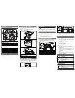
3.2 Dimensions and Fixing Points
EA
R
T
H
EA
R
T
H
BA
T
T
MO
N
AC
MO
N
+
25V
AUX
O/P
RELAY 1
RE
L
A
Y
1
RE
L
A
Y
2
RELAY 2
SOUNDER
OUTPUTS
POWER
LIMITED
+24V 0V A- A+ B- B+
COM
COM
N/C
N/C
N/O
N/O
ZX2Se
Only
400
40
0
35
0
25
25
280
140
60
A
A
Fuse
Fuse
Fuse
(FS1)
(FS2)
(FS3)
250V A/S
250V A/S
250V A/S
3.15A
1.6A
5.0A
FS
1
F
S
2
F
S
3
ISOLATE
ELSEWHERE
F1 T 2A H 250V
N
L
Figure 1 – Panel Fixing Centres – ZX1Se / ZX2Se
FS1 T 3.15A H 250V
N
L
500
215
180
500
43
0
35
Figure 2 – Panel Fixing Centres - ZX5Se


