24
3. TV Connections
DVI Video Device ( Cable Box, Satellite
Receiver, DVD Player, or Other Device)
Connect DVI devices (digital only) to the TV’s HDMI
input jacks.
Analog stereo audio cables and a DVI-to-HDMI cable or
DVI/HDMI adapter and HDMI cable are required.
Connect the DVI-to-HDMI cable (recommended) or
1.
HDMI cable with DVI/HDMI adapter from the DVI
device’s back panel to the TV’s HDMI jack.
Note:
If you are using a DVI/HDMI adapter, it is impor-
tant to connect the adapter to the DVI device for
best performance.
Connect a set of audio cables from
2.
AUDIO OUT
on the DVI device back panel to the
DVI/PC INPUT
AUDIO
on the TV main panel. Connect the red
cable to the
R
jack and the white cable to the
L
jack.
Note:
The HDMI connection supports copy protection
(HDCP).
Some devices require connection to an analog input
first in order to view on-screen menus and to select DVI
as the ouput. Please review your equipment instruc-
tions for DVI connectivity and compatibility.
INPUT 3
ANT-2/A
UX
ANT-1/MAIN
S-VIDEO
(INPUT 3)
DIGIT
AL
A
UDIO OUTPUT
INPUT
R
R
R
L
L
D
VI/PC INPUT
VIDEO
Y
Y/VIDEO
INPUT 1
Pb
P
r
Pb
YPbP
r(480i/480p/720p/1080i)
Pr
INPUT 2
- A
UDIO -
L
IR NetC
ommand
OUTPUT/
EX
TERNAL
C
ONTROLLER
A
VR A
UDIO
OUTPUT
R
L
- A
UDIO -
R
L
3D GL
ASSES EMIT
TER
VIDEO:
480i/480p/720p/1080i/1080p
A
UDIO:
PCM STEREO
INP
U
T
3
ANT-2
/AU
X
ANT-1
/MAI
N
S
-VIDE
O
(INPUT 3
)
DI
G
IT
A
L
A
UDI
O
O
UTPU
T
INPUT
R
R
R
L
L
D
VI/PC INPU
T
V
IDE
O
Y
Y
/VIDE
O
INPUT
1
Pb
Pr
Pb
Y
PbP
r(480i/480p/720p/1080i)
Pr
INP
U
T 2
- A
UDI
O
-
L
IR NetC
omman
d
O
UTPUT
/
EX
TERNAL
CO
NTR
O
LLE
R
A
VR A
U
DI
O
O
UTPUT
R
L
- A
UDI
O
-
R
L
3
D GL
ASSES EMIT
TE
R
VIDEO:
480i/480p/720p/1080i/1080p
A
U
DI
O:
P
C
M
S
TERE
O
D
VI/PC INPUT
- A
UDIO -
R
L
D
VI/PC INPUT
- A
UDIO -
R
L
DVI OUT
AUDIO
R
L
Digital DVI device
TV main
panel
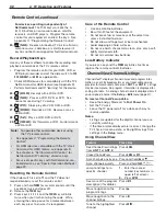
1.
1.
2.
2.
Figure 3. Connecting a digital DVI device
S-V ideo Device (Standard Cable Box,
Satellite Receiver, or Other Device)
Required: S-Video cable and left/right analog stereo
audio cables.
Connect an S-Video cable from
1.
S-VIDEO OUT
on
the cable box or satellite receiver back panel to
INPUT 3
S-VIDEO
on the TV main panel.
Connect left (white) and right (red) audio cables
2.
from
AUDIO OUT
on the cable box or satellite
receiver to
INPUT 3 AUDIO L
and
R
on the TV main
panel.
Connect the cable from the outside cable or satel-
3.
lite service to
CABLE IN
or
SATELLITE IN
on the
cable box or satellite receiver.
Note:
Refer to the cable box or satellite receiver
Owner’s Guide for cable or dish antenna con-
nections to the receiver.
INPUT 3
ANT-2/A
UX
ANT-1/MAIN
S-VIDEO
(INPUT 3)
DIGIT
AL
A
UDIO OUTPUT
INPUT
R
R
R
L
L
D
VI/PC INPUT
VIDEO
Y
Y/VIDEO
INPUT 1
Pb
P
r
Pb
YPbP
r(480i/480p/720p/1080i)
Pr
INPUT 2
- A
UDIO -
L
IR NetC
ommand
OUTPUT/
EX
TERNAL
C
ONTROLLER
A
VR A
UDIO
OUTPUT
- A
UDIO -
R
L
3D GL
ASSES EMIT
TER
A
UDIO:
PCM STEREO
PC:
V
GA,
W-V
GA,
SV
GA,
W-SV
GA,
X
GA,
W-X
GA,
SX
GA,
720p
, 1080p
IN
PU
T
3
A
NT-2
/AU
X
A
NT-1
/MAI
N
S
-VIDEO
(INPUT 3
)
DI
G
IT
AL
A
U
DI
O
OU
TP
UT
IN
PU
T
R
R
R
L
L
DV
I/
P
C
INPUT
V
IDE
O
Y
Y/
VIDE
O
INP
U
T 1
Pb
Pr
Pb
YPbP
r(480i/480
p
/720
p
/1080i
)
P
r
INP
U
T
2
- A
U
DI
O
-
L
IR Ne
tC
o
mm
a
n
d
O
UTPUT
/
E
XT
E
R
NAL
C
ONTROLLE
R
A
VR A
UDI
O
O
UTPUT
- A
U
DI
O
-
R
L
3
D GL
A
SS
E
S
EMIT
TE
R
A
UDIO:
PCM STERE
O
P
C:
V
GA,
W-V
GA,
SV
GA,
W-SV
GA,
X
GA,
W-X
GA,
SX
GA,
720p
, 1080
p
INPUT 3
R
L
- A
UDIO -
INPUT 3
R
L
- A
UDIO -
S-VIDEO
(INPUT 3)
S-VIDEO
(INPUT 3)
AUDIO
S-VIDEO
OUT
L
R
Any S-Video
device
TV main
panel
1.
1.
3.
2.
2.
CABLE IN or
SATELLITE IN
Incoming
cable from
wall
Connect audio
cables to INPUT
3 AUDIO
Figure 4. Connecting a device with S-Video
Содержание LaserVue L65-A90
Страница 1: ...MODEL L65 A90 Owner s Guide...
Страница 2: ......
Страница 70: ...70 Appendices This page intentionally left blank...
Страница 95: ......


