7 - 2
7.1 Power Supply Wiring
7.1 Power Supply Wiring
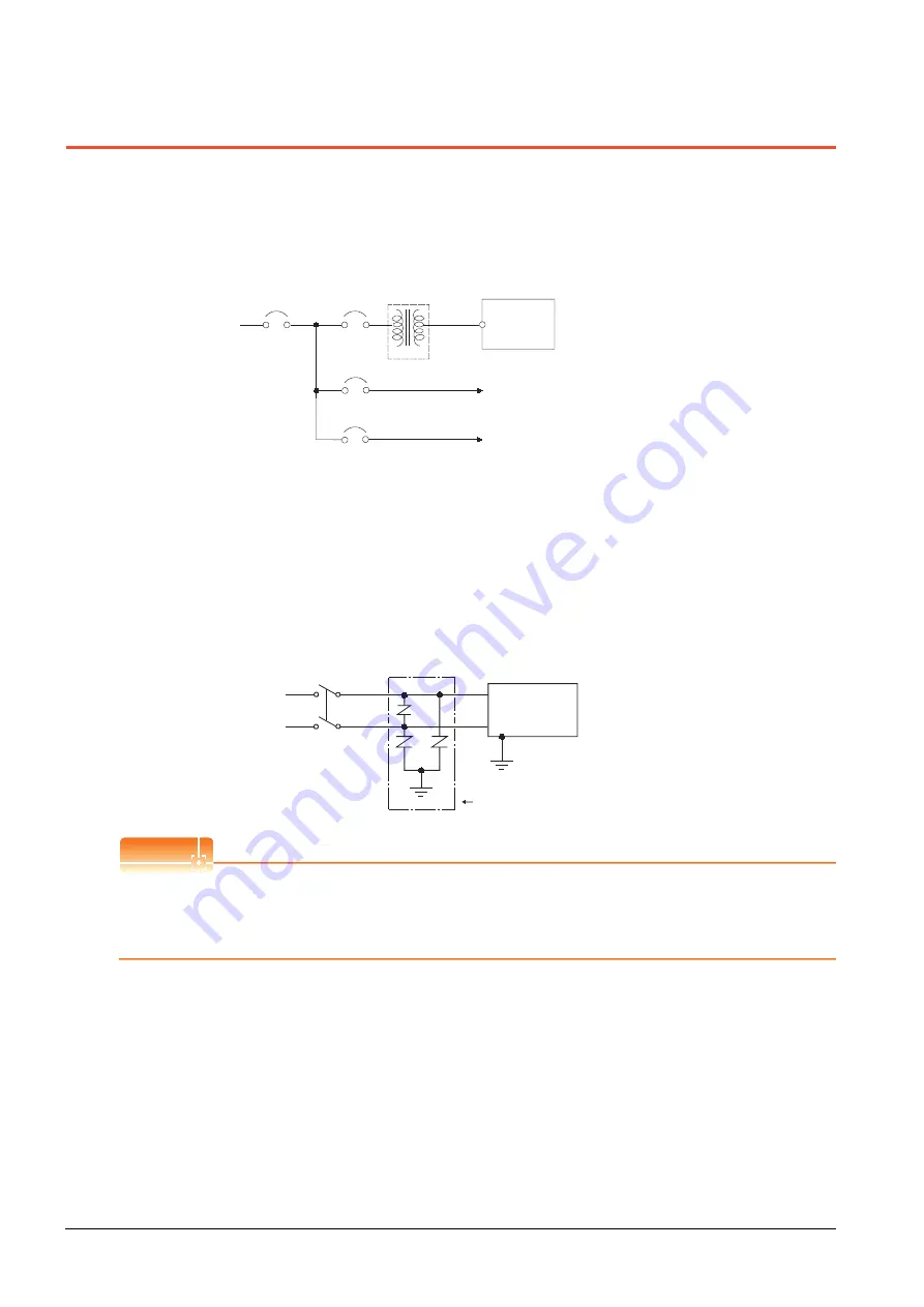
• Make wiring connections to the power supply, I/O equipment and power equipment separately by system as shown
below.
When frequent noise is identified, connect an isolation transformer.
Wiring diagram for power supply
• Twist 100V AC, 200V AC or 24V DC cable as closely as possible and connect the cable of the minimum length
between modules.
Also, use the thickest cable as possible (Max. 2mm
2
) to minimize the voltage drop.
Use M3 solderless terminals and securely tighten them with a tightening torque of 0.5 to 0.8N•m so that no problem
will result.
• Separate the 100V AC, 200V AC or 24V DC cable from the main circuit lines (high voltage, large current) and/or I/O
signal lines.
Keep a distance of 100mm or more.
• As measures against surge due to lightning, connect a lightning surge absorber as shown below.
Lightning surge absorber connection
POINT
POINT
POINT
(1) Separate the grounding of the lightning surge absorber (E1) from the grounding of the GOT (E2).
(2) Select an appropriate lightning surge absorber so that the supply voltage does not exceed the maximum
allowable circuit voltage of the surge absorber even when it rises to the maximum.
Main power
GOT
T1
I/O equipment
Main circuit equipment
Isolation
transformer
GOT
power
I/O power
Main circuit
power
AC
E2
E1
GOT
Lightning surge absorber
Содержание GOT 1000 GT16
Страница 1: ...GT16 User s Manual Hardware ...
Страница 2: ......
Страница 14: ...A 12 INDEX REVISIONS WARRANTY ...
Страница 193: ...10 3 Error Message and System Alarm 10 29 9 MAINTENANCE AND INSPECTION 10 TROUBLESHOOTING APPENDICES ...
Страница 210: ...App 17 ...
Страница 212: ...Index 2 Transportation Precautions App 15 U USB environmental protection cover 2 17 8 19 ...
Страница 217: ......


