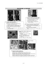


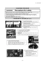


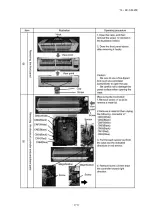


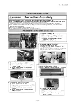

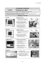

6. To remove the control box
(1) Remove the lid of control box.(See No.1)
(2) Pull off all the inserted connectors.
(3) Remove 2 cotrol box fixing screws and remove it.
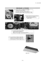
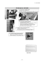
7. To remove the heat exchanger assembly
(1) Remove the bottom panel(B).(See No.3)
(2) Remove the drain pan.(See No.5)
(3) Remove the control box.(See No.6)
(4) Remove 4 pipe lid fixing screws and remove it.(
mark)
(5) Remove 4 heat exchanger assy fixing screws and
remove it.(
mark)
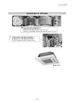
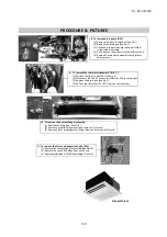
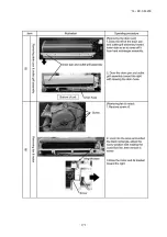
8. To remove the drain pump(DM) and flot switch(FS)
(1) Remove the control box.(See No.6)
(2) Disconnect the drain pump connector(CNR)
on PCB in control box.
(3) Disconnect the flot switch connector(CNI)
on PCB in control box.
(4) Remove 4 drain pump assembly fixing screws
and remove it.(
mark)
(5) Pull a hose to the arrow direction and remove it.
(6) Remove 3 drain pump fixing screws and
remove it.(
mark)
(7) Remove the flot switch fixing screw and
remove it.(
mark)
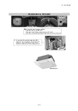
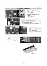
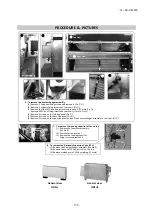
9. To remove the electronic expansion Valve (EEV)
(1) Remove the heat exchanger assembly.
(See No.7)
(2) Remove the coil of EEV by pull out
on the top.
(3) Remove welded part of EEV by welding.
(
mark)
10. To remove the thermistors (example"Thi-R1")
(1) Remove the lid of control box.(See No.1)
(2) Disconnect the Thi-R1 connector(CNN) on PWB in control box.
(3) Remove the drain pan.(See No.5)
(4) Pull out the thermistor"Thi-R3" from the sensor holder.
PROCEDURE & PICTURES
Pipe lid
EEV
Coil of EEV
General view
'14 • KX-SM-200
–
1
6
6
–
Содержание FDC1000KXZWE1
Страница 122: ... 14 KX SM 200 120 PCB003Z842 A 3 ELECTRICAL WIRING Models FDC224KXZWE1 280KXZWE1 335KXZWE1 3 phase 380 415V 50Hz ...
Страница 171: ... 14 KX SM 200 169 ...
Страница 172: ... 14 KX SM 200 170 ...
Страница 173: ... 14 KX SM 200 171 ...
Страница 174: ... 14 KX SM 200 172 ...


