
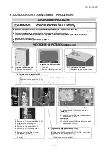

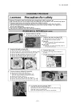


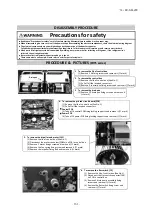
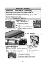


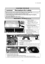

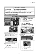
Precautions for safety
Read these "Precautions for safety" carefully before starting disassembly work and do it in the proper way.
When disassembling, be sure to turn off the power. When disassembling the electrical components, check the electrical wiring diagram.
The electrical components are under high voltage by the operation of the booster capacitor.
Fully discharge the capacitor before commencing a repair work. Failure to observe this warning could result in electric shock.
When parts of refrigerant cycle is disassembled by welding, be sure to work after collecting a refrigerant, if the refrigerant isn't
collected, the unit might explode.
Be sure to collect refrigerant without spreading it in the air.
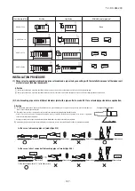
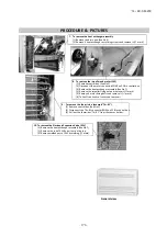
These contents are an example. Please refer to a similar part of actual unit.
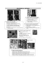
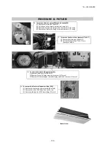
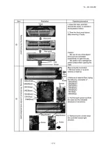
1. To remove the lid of control box
(1) Remove 2 lid fixing screws and remove it.(
mark)
2. To remove the control box
(1) Remove the lid of control box.(See No.1)
(2) Pull off all the inserted connectors.
(3) Remove 2 control box fixing screws and remove it.(
mark)
3. To remove the drain pan
(1) Remove 10 drain pan fixing screws and remove it.
(
mark)
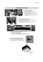
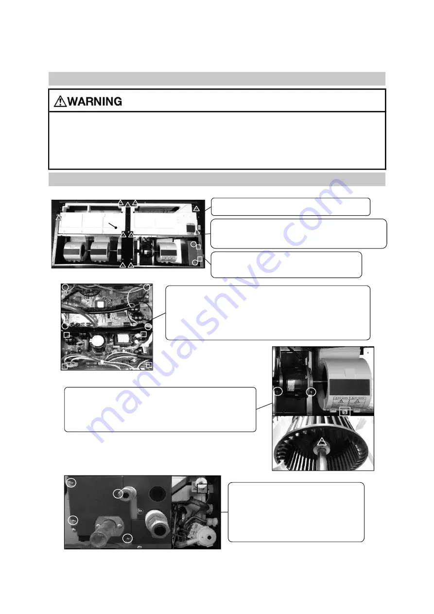
4. To remove the printed circuit board (PCB)
(1) Remove the lid of control box.(See No.1)
(2) Pull off all the inserted connectors.
Control PCB
(3) Take off 4 control PCB fixing locking supports and remove it.(
mark)
Power PCB
(4) Take off 4 power PCB fixing locking supports and remove it.(
mark)
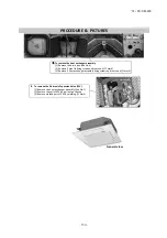
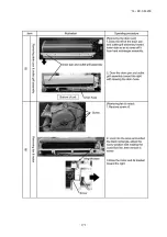
5. To remove the impeller and motor (FM)
(1) Remove the lid of control box.(See No.1)
(2) Disconnect the motor connector(CNMx) on PCB in control box.
(3) Remove 2 motor fixings screw and remove it.(
mark)
(4) Remove the fan casing fixing screw and remove it.(
mark)
(5) Remove the impeller fixing bolt and remove it.(
mark)
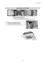
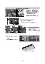
6. To remove the flot switch (FS)
(1) Remove the lid of control box.(See No.1)
(2) Disconnect the flot switch connector(CNI)
on PCB in control box.
(3) Remove 4 drain pump assembly fixing
screws and remove it.(
mark)
(4) Remove the flot switch fixing screw and
remove it.(
mark)
DISASSEMBLY PROCEDURE
PROCEDURE & PICTURES
(FDTS series)
Drain pan
c
Conrtol PCB
Power PCB
'14 • KX-SM-200
–
1
6
1
–
Содержание FDC1000KXZWE1
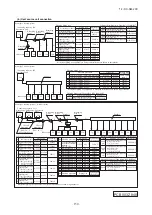
Страница 122: ... 14 KX SM 200 120 PCB003Z842 A 3 ELECTRICAL WIRING Models FDC224KXZWE1 280KXZWE1 335KXZWE1 3 phase 380 415V 50Hz ...
Страница 171: ... 14 KX SM 200 169 ...
Страница 172: ... 14 KX SM 200 170 ...
Страница 173: ... 14 KX SM 200 171 ...
Страница 174: ... 14 KX SM 200 172 ...


