


'14 • KX-SM-200
–
138
–
③
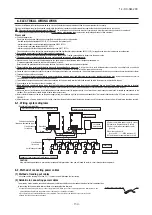
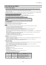
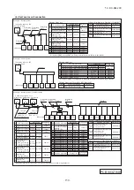
Turn on power in order from the heat source unit to indoor units. Give one-minute or longer interval for them.
When there are some units not supporting new SL connected in the network, set SW5-5 to ON to choose the previous SL communication mode.
In the case of previous SL, the maximum number of indoor units connectable in a network is 48.
Heat source unit(Master)
SW4-7 OFF
Heat source unit No.20
Indoor unit
Heat source unit No.20
Indoor unit No.01
Indoor unit
Heat source unit No.20
Indoor unit No.02
Indoor unit
Heat source unit No.20
Indoor unit No.03
Indoor unit
Heat source unit No.22
Indoor unit No.04
Indoor unit
Heat source unit No.22
Indoor unit No.05
Indoor unit
Heat source unit No.22
Indoor unit No.06
Heat source unit(Master)
SW4-7 OFF
Heat source unit No.22
Heat source unit(Slave)
SW4-7 ON
Heat source unit No.20(21)
Heat source unit(Slave)
SW4-7 ON
Heat source unit No.22(23)
Slave setting
※
The same setting with the master unit’s address number
(In the network, “the setting
+
1” is assigned.)
indicates signaling wires (A/B).
indicates refrigerant piping.
Example of address setting (manual)
Take care not to assign an address duplicating with
one used in another system.
(Use every second number in setting an address)
Set a heat source unit number in the system
Take care not to assign a duplicating address in a network.
Indoor unit address setting
000
ー
127[47]
000
000
00
ー
31[47]
49
49
Indoor unit address setting
00
ー
47
49
×
00
ー
47
49
×
00
ー
31[47]
49
00
ー
31
Heat source unit address setting
00
ー
47
49
×
Heat source unit address setting
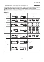
●
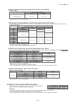
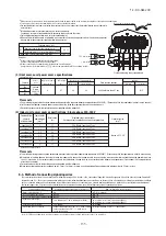
Summary of address setting methods (figures in [ ] should be used with previous SL)
Do not set numbers other than those shown in the table, or an error may be generated.
Note: When units supporting new SL are added to a network using previous SL such as one involving FD
○
A
△△
KXE4.5 series units, choose previous SL for the communication protocol and set addresses
manually.
Since the models FDT224 and 280 have 2 PCBs per unit, set different indoor unit No. and SW on each PCB.
●
Heat source unit No., which is used to identify which heat source unit and indoor units are connected in a refrigerant system, is set on heat source unit PCB and indoor unit PCB. Give the same heat
source unit No. to all heat source unit and indoor units connected in same refrigerant system.
●
An indoor unit No. is used to identify individual indoor units. Assign a unique number that is not assigned to any other indoor units on the network.
Manual address setting
(previous SL/new SL)
Units supporting new SL
Units NOT supporting new SL
Automatic address setting for
multiple refrigerant systems installation
(with new SL only)
Automatic address setting for
single refrigerant system installation
(previous SL/new SL)
Indoor No. switch
Heat source No. switch
Heat source No. switch
Indoor No. switch
Heat source No. switch
Heat source No. switch
Unless stated otherwise, the following procedures apply, when new SL is chosen for the communication protocol.
When previous SL is chosen, use figures shown in [ ] in carrying out these procedures.
Manual address setting Generally applicable to new SL/previous SL, use figures in [ ] with previous SL.
Automatic address setting Generally applicable to new SL/previous SL, use figures in [ ] with previous SL.
With new SL, you can set indoor unit addresses automatically even for an installation involving multiple refrigerant systems connected with same network, in addition to the conventional automatic
address setting of a single refrigerant system installation.
However, an installation must satisfy some additional requirements such as for wiring methods, so please read this manual carefully before you carry out automatic address setting.
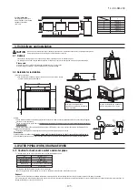
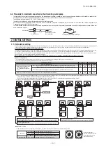
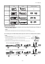
(1) In the case of a single refrigerant system installation
(Generally applicable to new SL/previous SL, use figures in [ ] with previous SL.)
②
Indoor unit address setting
Set as follows before you turn on power.
Make sure that the
Indoor Unit No. switch
is set to
000 [in the case of previous SL: 49] (factory setting).
Make sure that the
Heat source Unit No. switch
is set to
49 (factory setting).
③
Turn on power in order from the heat source unit to indoor units. Give one-minute or longer interval for them. Unlike the procedure set out in (2) below, you need not change settings from the 7-
segment display panel.
④
Make sure that the number of indoor units indicated on the 7-segment display panel agrees with the number of the indoor units that are actually connected to the refrigerant system.
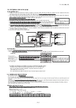
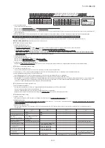
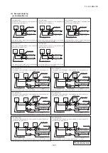
(2) In the case of a multiple refrigerant systems installation
(Applicable to new SL only. In the case of previous SL, set addresses with some other method.)
(This option is available when the interconnection wiring among refrigerant systems is on the heat source unit side and new SL is chosen as the communication protocol.)
②
Address setting of indoor unit
Set as follows before you turn on power.
Make sure that the
Indoor Unit No. switch
is set to
000 (factory setting).
Make sure that the
Heat source Unit No. switch
is set to
49 (factory setting).
③
Isolate the present refrigerant system from the network.
Disengage the
network connectors (white 2P)
of the heat source units. (Turning on power without isolating each refrigerant system will result in erroneous address setting.)
[STEP2]
(Power on and automatic address setting)
④
Turn on power to the heat source unit
Turn on power in order from the heat source unit to indoor units. Give one-minute or longer interval for them.
⑤
Select and enter “1” in P31 on the 7-segment display panel of each heat source unit (master unit in case of combination) to input “Automatic address start.”
⑥
Input a starting address and the number of connected indoor units.
Input a starting address in P32 on the 7-segment display panel of each heat source unit (master unit in case of combination).
⑦
When a starting address is entered, the display indication will switch back to the “Number of Connected Indoor Units Input” screen.
Input the number of connected indoor units from the 7-segment display panel of each heat source unit (master unit in case of combination). Please input the number of connected indoor units
(on the same refrigerant line in case of combination) for each heat source unit. (You can input it from P33 on the 7-segment display panel.)When the number of connected indoor units is
entered, the 7-segment display panel indication will switch to “AUX” and start flickering.
[STEP3]
(Automatic address setting completion check)
⑧
Indoor unit address determination
When the indoor unit addresses are all set, the 7-segment display panel indication will switch to “AUE” and start flickering.
If an error is detected in this process, the display will show “A
○○
.”
Check the 7-segment display panel of each heat source unit (master unit in case of combination).
Depending on the number of connected indoor units, it may take
about 10 minutes
before the indoor unit addresses are all set.
[STEP4]
(Network definition setting)
⑨
Network connection
When you have confirmed an “AUE” indication on the display of each heat source unit,
engage the network connectors
again.
⑩
Network polarity setting
After you have made sure that the network connectors are engaged,
select and enter “1” in P34 on the 7-segment display panel of
any heat source unit (on only 1 unit : master unit
in case of combination)
to specify network polarity.
⑪
Network setting completion check
When the network is defined, “End” will appear on the 7-segment display panel. An “End” indication will go off, when some operation is made from the 7-segment display panel or
3 minutes after.
Address setting procedure
(perform these steps for each heat source unit)
[STEP1]
(Items set before turning on power)
①
Address setting of heat source unit
Set as follows before you turn on power.
Set
the Heat source Unit No. switch
to a number
00 - 31
. Set a unique number by avoiding the numbers assigned to other heat source units on the network.
●
Similarly for the master unit used in a combined installation, set
the Heat source Unit No. switch to a number 00-31.
●
For slave units of combination,
set the rotary switches for heat source No. at
the same heat source No. as the master unit of combination.
When 2 units are combined, set the dip switch SW4-7 of slave unit to ON. When 3 units are combined, set the dip switch SW4-7 of slave unit 1 to ON and the dip switch SW4-8
of slave unit 2 to ON.
(Use same setting for heat source No. of master unit and slave unit.)
②
OFF
①
OFF
②
indoor000/heat source 49
(
factory setting
)
①
01,03(Ex
)
③
Disconnect (each heat source unit)
STEP1
STEP2
STEP3
STEP4
ー
ー
ー
ー
⑨
Connect(each heat source unit)
ー
ー
ー
⑩
Set in P34 on the 7-segment display
panel of any heat source unit.
⑪「
End
」
ー
ー
ー
ー
ー
ー
ー
ー
ー
⑧
“AUE”(blink), or “A
○○
” in error events.
Indoor unit power source
Heat source unit power source
Indoor unit
(indoor/heat source No.SW)
Heat source unit (heat source No.SW)
Network connectors
Start automatic address setting
Set starting address
Set the number of indoor unit
Polarity setting
7-segment display
④
ON
④
ON
⑦
heat source 01:
「
03
」
(Ex)
heat source 03:
「
03
」
(Ex)
⑥
heat source 01:
「
01
」
(Ex)
heat source 03:
「
04
」
(Ex)
⑤
Select “Automatic Address Start”
on each heat source unit.
⑦[
AUX
]
(Blink
)
ー
ー
ー
ー
Refrigerant pipe
Indoor unit
Indoor unit
Indoor unit
Indoor unit
Indoor unit
Indoor unit
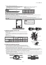
Address change (available only with new SL)
・
Within a refrigerant system, indoor units are assigned addresses in the order they are recognized by the heat source unit. Therefore, they are not necessarily assigned addresses
in order from the nearest to the heat source unit first as depicted in drawings above.
・
Make sure that power has been turned on to all indoor units.
・
When addresses are set, you can have the registered indoor unit address No. and the heat source unit address No. displayed on the remote control unit by pressing its CHECK
button.
・
Automatic address setting can be used for an installation in which prulal indoor units are controlled from one remote control unit.
・
Once they are registered, addresses are stored in microcomputers, even if power is turned off.
・
If you want to change an address after automatic address setting, you can change it from the remote control unit with its “Address Change” function or by means of manual
setting. Set a unique address by avoiding the address assigned to other indoor unit on the network when the address is changed.
・
Do not turn on power to centralized control equipment until automatic address setting is completed.
・
When addresses are set, be sure to perform a test run and ensure that you can operate all indoor and heat source units normally. Also check the addresses assigned to the indoor
units.
[
STEP1
]
[
STEP2
]
[
STEP3
]
[
STEP4
]
Indoor No.SW
000
000
Heat source No.SW
49
49
Indoor unit address setting
Heat source unit address setting
Heat source No.SW
49
00
-
31
“Address Change” is used,
when you want to change an indoor unit address assigned with the “Automatic Address Setting” function from a remote control unit
.
Accordingly, the conditions that permit an address change from a remote control unit are as follows.
If “CHANGE ADD.
▼
” is selected with some addresses falling outside these conditions, the following indication will appear for 3 seconds on the
remote control ”INVALID OPER” .
Automatic address setting for multiple refrigerant systems installation
Automatic address setting forsingle refrigerant system installation
SW4-7 0FF
SW4-7 ON
SW4-7 0FF
SW4-7 ON
SW4-7 0FF
SW4-7 ON
SW4-7 0FF
SW4-7 ON
SW4-7 0FF
SW4-7 ON
SW4-7 0FF
SW4-7 ON
Start [01]
Number [03]
Start [04]
Number [03]
Indoor unit
(
00
)
+01
Indoor unit
(
01
)
+01
Indoor unit
(
02
)
+01
Indoor unit
(
00
)
+04
Indoor unit
(
01
)
+04
Indoor unit
(
02
)
+04
Indoor unit
01
Indoor unit
02
Indoor unit
03
Indoor unit
04
Indoor unit
05
Indoor unit
06
SW4-7 0FF
SW4-7 ON
SW4-7 0FF
SW4-7 ON
Indoor unit
01
Indoor unit
02
Indoor unit
03
Indoor unit
04
Indoor unit
05
Indoor unit
06
Heat source unit
(Master) [01]
Heat source unit
(Slave) [01 (02)]
Heat source unit
(Master) [03]
Heat source unit
(Slave) [03 (04)]
Heat source unit
(Master) [01]
Heat source unit
(Slave) [01 (02)]
Heat source unit
(Master) [03]
Heat source unit
(Slave) [03 (04)]
Heat source unit
(Master) [01]
Heat source unit
(Slave) [01 (02)]
Heat source unit
(Master) [03]
Heat source unit
(Slave) [03 (04)]
Heat source unit
(Master) [01]
Heat source unit
(Slave) [01 (02)]
Heat source unit
(Master) [03]
Heat source unit
(Slave) [03 (04)]
Network connector
The switch will continuously change the display indication to the next one in every 0.25 seconds when it is pressed for 0.75 seconds or longer.
If the Reset switch is pressed during an operation, the display indication returns to the one that was shown before the last Set switch operation.
Even if an indoor unit No. is changed in this mode, the registered indoor unit No. before address change mode is displayed when [I/U SELECTION
▼
] is shown.
When “SET COMPLETE” is shown, indoor unit No. is registered.
(2) When plural indoor units are connected to the remote control.
When plural indoor units are connected, you can change their addresses without altering their cable connection.
Address change mode
Selecting an indoor unit
to be changed address
Setting a new indoor unit No.
1
2
3
Setting a new heat source
unit No.
Ending the session
4
5
①
Press the AIR CON Unit No. switch for 3 seconds or longer.
②
Each time when you press the switch, the display indication will be switched.
③
Press the SET switch when the display shows “CHANGE ADD.
▼
”
The lowest indoor unit No. among the indoor units connected to the remote control unit will be shown.
④
Pressing the switch will change the display indication cyclically to show the unit No.’s
of the indoor units connected to the remote control and the unit No.’s of the heat source
units connected with them.
⑤
Then the address No. of the indoor unit to be changed is determined and the screen switches to the
display “ SET I/U ADD.”
⑥
Set a new indoor unit No. with the switch.
A number indicated on the display will increase or decrease by 1 upon pressing the
▲
or
▼
switch
respectively.
⑦
After selecting an address, press the SET switch. Then the address No.of the indoor unit is determined.
⑧
The display will indicate the determined indoor address No. for 2 seconds and then switch to the
“ SET O/U ADD.” screen.
A default value shown on the display is the current address.
⑨
Set a new heat source unit No. with the switch.
A number indicated on the display will increase or decrease by 1 upon pressing the
▲
or
▼
switch
respectively.
⑩
After selecting an address, press the SET switch.
Then the address of the indoor unit and heat source unit are determined.
⑪
If you want to continue to change addresses, return to step
④
.
⑫
If you want to end the session (and reflect new address settings)
In Step
⑩
, press the
▼
switch to select “END
▲
.”
If you have finished changing addresses, press the SET switch while “END
▲
” is shown. While new
settings are being transmitted, “SET COMPLETE” will be indicated. Then the remote control display will
change to the normal state.
⑬
If you want to end the session (without reflecting new address settings)
Before you complete the present address setting session, press the “ON/OFF” switch.
Then the display is change to exit from this mode and switch the display to the normal state.
All address settings changed in the session will be aborted and not reflected.
[
I/U
002
]
(2sec)
[
I/U 002
]
(2sec lighting)
⇔[
SET O/U ADD.
]
(1sec)
⇔[
O/U
01
]
(Blink)
[
O/U
00
▲]
⇔[
O/U
01
]
⇔[
O/U
02
]
⇔ ・・・
⇔[
O/U
31
▼]
[
I/U 002
O/U 02
]
(2sec lighting)
→[
SELECT
]
(1sec lighting)
→[
I/U SELECTION
▼]
(lighting)
[
Press the switch
]
(1sec)
→[
SET COMPLETE
]
(2
-
10sec
lighting)
[
END
▲]
→[
SET COMPLETE
]
(2
-
10sec lighting)
→
Normal state
[
ON/OFF
]
→
Forced termination
[
SELECT I/U
]
(1sec)
→[
I/U 001 O/U 01
▲]
(Blink)
[
CHANGE ADD
▼]
⇔[
MASTER I/U
▲]
[
CHANGE ADD
▼]
[
I/U 001 O/U 01
▲」
⇔[
I/U 002
O/U 01
]
⇔[
I/U 003
O/U 01
]
⇔ ・・・
⇔[
I/U 016 O/U 01
▼」
[
SET I/U ADD.
]
(1sec)
→[
I/U 001
]
(Blink)
[
I/U
000
▲]
⇔[
I/U
001
]
⇔[
I/U
002
]
⇔ ・・・
⇔[
I/U
127
▼]
Turn on power to centralized control equipment after the addresses are determined.
Turning on power in wrong order may result in a failure to recognize addresses.
Item
Operation
Display
NOTICE
⑦
Set a new heat source unit No. with the
switch.
A number indicated on the display will increase or decrease by 1 upon pressing the
▲
or
▼
switch respectively.
[
I/U 000
▲」
⇔
[
I/U 001
]
⇔
[
I/U 002
]
⇔ ・・・
⇔
[
I/U 127
▼
]
[
I/U 002] (2sec Lighting)
→
[ SET O/U ADD.]
(1sec)
→
[
O/U 01
]
(Blink)
[
I/U 001
O/U 01] (1sec)
→
[ SET I/U ADD.]
(1sec)
→
[
I/U
001
]
(Blink)
④
Set a new indoor unit No. with the
switch.
A number indicated on the display will increase or decrease by 1 upon pressing the
▲
or
▼
switch respectively.
Item
Operating procedure
When the eco touch remote control is connected, refer to the installation setting in the installation manual which is packed along with the remote control.
(1) When single indoor unit is connected to the remote control.
Address change mode
To set a new indoor unit No.
To set a new heat source
unit No.
1
2
3
①
Press the AIR CON No. switch for 3 seconds or longer.
②
Each time when you press the
switch, the display indication will be switched.
[
O/U 00
▲
]
⇔
[
O/U 01
]
⇔
[
O/U 02
]
⇔ ・・・
⇔
[
O/U 31
▼
]
Operation
Display
③
Press the SET switch when the display shows “CHANGE ADD.
▼
”
and then start the address change mode, changing the display indication to the “Indoor Unit No.
Setting” screen from the currently assigned address.
⑤
After selecting an address, press the SET switch, and then the indoor unit address No. is defined.
⑥
After showing the defined indoor address No. for 2 seconds, the display will change to the “heat
source Address No. Setting” screen.
The currently assigned address is shown as a default value.
⑧
After selecting an address, press the SET switch, and then the heat source unit No. and the
indoor unit No. are defined.
[CHANGE ADD.
▼
]
[CHANGE ADD.
▼
]
⇔
[MASTER I/U
▲
]
[
I/U 002 O/U 02] (2sec Lighting)
→
[
SET COMPLETE] (2sec Lighting)
→
Returns to normal condition.
[
I/U 002] (2sec)
Note:
Slave unit address is master unit +1. Address of second slave unit is master
unit +2. When setting the address for master unit, take care to avoid
duplication with other systems. Otherwise, it cannot operate. (Error: E-31)
①
Address setting of heat source unit Before turning on the power, set as follows. The heat source unit address is registered when the power is turned on.
Set
the heat source No. switches
in a range of
00 – 31 [or 00 - 47 for old SL].
Take care not to duplicate with other heat source unit No. on the network.
In the same way also on the master unit of combination,
set the rotary switch for heat sorce No.
in a range of 00 - 31 [or 00 – 47 for old SL]
For slave units of combination,
set the rotary switches for heat source No. at
the same heat source No. as the master unit of combination.
When 2 units are combined, set the dip switch SW4-7 of slave unit to ON. When 3 units are combined, set the dip switch SW4-7 of slave unit 1 to ON
and the dip switch SW4-8 of slave unit 2 to ON.
(Use same setting for heat source No. of master unit and slave unit.)
Above list is an example.
The address on the network is master unit
+1 for the slave unit.
If the slave unit address is larger than 31 [or 47 for old SL], the
address is assigned sequentially starting from 00.
When setting sequential addresses, take care not to duplicate the
master unit address in the refrigerant system B with addresses of
slave units in the refrigerant system A.
Heat source unit
Master
Slave
Master
Slave
Master
Slave
SW1
2
2
2
2
3
3
SW2
2
2
4
4
1
1
SW4-7
OFF
ON
OFF
ON
OFF
ON
Address on network
22
23
24
25
31
00
Refrigerant system
A
B
C
Heat source unit
Master
Slave 1
Slave 2
Master
Slave 1
Slave 2
Master
Slave 1
Slave 2
SW1
2
2
2
2
2
2
3
3
3
SW2
2
2
2
5
5
5
1
1
1
SW4-7
OFF
ON
OFF
OFF
ON
OFF
OFF
ON
OFF
SW4-8
OFF
OFF
ON
OFF
OFF
ON
OFF
OFF
ON
Address on network
22
23
24
25
26
27
31
00
01
Refrigerant system
A
B
C
②
Address setting of indoor unit
Before turning on the power, set as follows. Indoor address is registered when the power is turned on.
Set
the indoor No. switch
in a range of
000 – 127 [or 00 – 47 for old SL].
For
the heat source No. switches,
set corresponding heat source No. in a range of
00 – 31 [or 00 – 47 for old SL)].
Set with care not to duplicate with other indoor No. on the network.
CAUTION
If the slave unit is not
specified, a compressor
failure may result.
t
In the same way also on the master unit of combination,
confirm that the rotary switch for heat source No. is set
at 49 by the default.
t
In the same way also on the slave unit of combination,
confirm that the rotary switch for heat source No. is set
at 49 by the default.
When 2 units are combined, set the dip switch SW4-7 of slave unit to ON. When 3 units are combined, set the dip switch 4-7 of slave unit 1 to ON
and the dip switch SW4-8 of slave unit 2 to ON.
Heat source unit
Master
Slave
SW1
4
4
SW2
9
9
SW4-7
OFF
ON
Address on network
49
00
Heat source unit
Master
Slave 1
Slave 2
SW1
4
4
4
SW2
9
9
9
SW4-7
OFF
ON
OFF
Address on network
49
00
01
①
Address setting of heat source unit Before turning on the power, set as follows.
Confirm that
the heat source No. switch
is set
at 49 by the default.
SW4-8
OFF
OFF
ON
Содержание FDC1000KXZWE1
Страница 122: ... 14 KX SM 200 120 PCB003Z842 A 3 ELECTRICAL WIRING Models FDC224KXZWE1 280KXZWE1 335KXZWE1 3 phase 380 415V 50Hz ...
Страница 171: ... 14 KX SM 200 169 ...
Страница 172: ... 14 KX SM 200 170 ...
Страница 173: ... 14 KX SM 200 171 ...
Страница 174: ... 14 KX SM 200 172 ...


