5. PARAMETERS
5 - 8
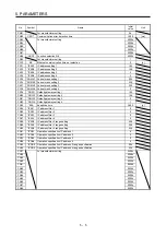
5.2.3 Network setting parameters ([Pr. PN_ _ ])
No./symbol/
name
Setting
digit
Function
Initial
value
[unit]
PN02
CERT
Communication
error detection
time
Set the time until [AL. 86.1 Network communication error 1] is detected.
Setting "0" disables the detection of [AL. 86.1 Network communication error 1].
This parameter can be used only when CC-Link IE Field Network Basic is set.
Setting range: 0 to 1000
1000
[ms]
PN08
*NOP8
Function
selection N-8
_ _ _ x Command interface selection
Set the command interface in the positioning mode. The setting of this digit is
disabled in the position control mode, speed control mode, torque control mode, and
profile mode.
0: General-purpose interface
1: Communication interface
0h
_ _ x _ For manufacturer setting
0h
_ x _ _
0h
x _ _ _ Communication function selection
0: Ethernet communication (CC-Link IE field network Basic, SLMP, and
Modbus/TCP)
1: RS-485 communication (Modbus RTU)
Communications other than selected communication function are unavailable.
0h
PN10
*CONN
Ethernet
communication
time-out
selection
Set the time until [AL. 86.4 Network communication error 4] is detected.
Setting "0" disables the detection of [AL. 86.4 Network communication error 4].
This parameter is enabled with SLMP and Modbus/TCP.
The detection of [AL. 86.4] starts when SLMP or Modbus/TCP is received for the first
time. When an alarm is detected and then reset, the detection stops and will restart
upon receipt of the next SLMP or Modbus/TCP.
This parameter can be used on servo amplifiers with software version A4 or later.
This parameter cannot be used when Modbus RTU is set.
Setting range: 0 to 60
0
[s]
PN11
*IPAD1
IP address
setting 1
Set the 1st octet of the IP address in decimal.
Set the IP address assigned by the network administrator.
When SLMP command (IPAdressSet) is received, the setting of the first octet is
written to this parameter.
Refer to table 5.1 for the relation between the setting value of the identification
number setting rotary switch and the parameter setting value.
This parameter cannot be used when Modbus RTU is set.
Setting range: 0 to 255
192
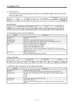
Table 5.1 Relation between IP address setting and identification number setting rotary switch
Identification number
setting rotary switch
(SW1/SW2)
IP address
00h
1st octet
The setting value of [Pr. PN11] is used.
2nd octet
The setting value of [Pr. PN12] is used.
3rd octet
The setting value of [Pr. PN13] is used.
4th octet
The setting value of [Pr. PN14] is used.
01h to FFh
1st octet
The setting value of [Pr. PN11] is used.
2nd octet
The setting value of [Pr. PN12] is used.
3rd octet
The setting value of [Pr. PN13] is used.
4th octet
The setting value of the identification number setting
rotary switch (SW1/SW2) is used.
Содержание MR-JE-C Series
Страница 9: ...A 8 MEMO ...
Страница 13: ...4 MEMO ...
Страница 33: ...2 CC Link IE Field Network Basic SLMP 2 16 MEMO ...
Страница 73: ...5 PARAMETERS 5 14 MEMO ...
Страница 79: ...6 MANUFACTURER FUNCTIONS 6 6 MEMO ...
Страница 143: ...MEMO ...


