background image

7. OBJECT DICTIONARY 

7 -  22 


Index 

Sub Index 

Name and function 

Data 

Type 

Access 

Variable  mapping 

Default 

Range 

Units 

EEP-ROM 

Parameter 

No. of points/No. 

of Registers 

Continuous read/  continuous write 

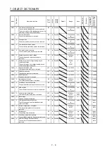
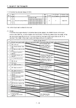
60F2 

0  Positioning option code 

Set the profile position mode. 
Bit 1 to Bit 3 always report "0". Setting a value 

other than "0" causes an error. 
 
[Bit 1 / Bit 0: relative option] 
Specify how to handle the relative position 

command during pp. 

00: The positioning moves with the relative 

position from the internal absolute target 

position. 

 
[Bit 3 / Bit 2: change immediately option] 
The change set immediately (Controlword bit 

5) at pp = Specify the behavior of 1. 
00: Standard operation of pp mode 

(Immediately reflects new Target position, 

profile velocity, acceleration etc). 

 
[Bit 7 / Bit 6: rotary axis direction option] 
Specify the operation of the rotation axis 

during pp and pt. 
00: Rotating to the target position in a direction 

specified with a sign of the position data. 

01: Regardless of the sign of the position data, 

the servo motor rotates in the address 

decreasing direction. 

10: Regardless of the sign of the position data, 

the servo motor rotates in the address 

increasing direction. 

11: The servo motor rotates from the current 

position to the target position in the shorter 

distance direction. In addition, if the 

distances from the current position to the 

target position are the same for CCW and 

CW, the servo motor rotates in the CCW 

direction. 

U16 

rw  Possible 

0000h 

0000h to 

00C0h 


  PT03 

1  Impos-

sible 

60F4 

0  Following error actual value 

The droop pulses are returned. 

I32 

ro  Possible 


-2147483648 

to 

2147483647 

pos units   


2  Impos-

sible 

60FA 

0  Control effort 

The speed command is returned. 

I32 

ro  Possible 

-2147483648 

to 

2147483647 

0.01 

r/min 


2  Impos-

sible 

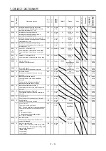
60FF 

0  Target velocity 

Set the speed command used in the profile 

velocity mode (pv). 

I32 

rw  Possible 

-2147483648 

to 

2147483647 

0.01 

r/min 


2  Impos-

sible 

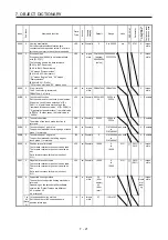
6502 

0  Supported drive modes 

The supported control mode is returned. 
Depending on the servo amplifier software 

version, the "Default" value and "Range" value 

are different. Refer to section 7.6.9 for details. 
Bit 0: Profile position mode (pp) 
Bit 2: Profile velocity mode (pv) 
Bit 3: Profile torque mode (tq) 
Bit 5: Homing mode (hm) 
Bit 16: Jog mode (jg) 
Bit 17: Point table mode (pt) 
Bit 19: Indexer mode (idx) 

U32 

ro  Possible  0000002Dh 

(A3 or 

earlier) 

000B002Dh 

(A4 or later) 

0000002Dh 

(Fixed) 

(A3 or 

earlier) 

000B002Dh 

(Fixed) 

(A4 or later) 


2  Impos-

sible 


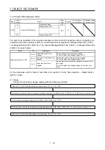
Note   1.  This object can be used on the servo amplifiers with software version A3 or later. 
 

  2.  This object can be used on the servo amplifiers with software version A4 or later. 


  3.  For servo amplifiers with software version A3 or earlier, the range of Sub Index is 1 to 39. 


Содержание MR-JE-C Series

Страница 1: ...without notice This Instruction Manual uses recycled paper MODEL MODEL CODE General Purpose AC Servo MR JE _C SERVO AMPLIFIER INSTRUCTION MANUAL Network HEAD OFFICE TOKYO BLDG MARUNOUCHI TOKYO 100 8310 MODEL MR JE _C SERVO AMPLIFIER INSTRUCTION MANUAL Network Ethernet Interface C C ...

Страница 2: ... or severe injury CAUTION Indicates that incorrect handling may cause hazardous conditions resulting in medium or slight injury to personnel or may cause physical damage Note that the CAUTION level may lead to a serious consequence according to conditions Please follow the instructions of both levels because they are important to personnel safety What must not be done and what must be done are ind...

Страница 3: ...g them directly or close to combustibles will lead to smoke or a fire Always connect a magnetic contactor between the power supply and the power supply L1 L2 L3 of the servo amplifier in order to configure a circuit that shuts down the power supply on the side of the servo amplifier s power supply If a magnetic contactor is not connected continuous flow of a large current may cause smoke or a fire...

Страница 4: ...avy load on the equipment Otherwise it may cause injury The equipment must be installed in the specified direction Leave specified clearances between the servo amplifier and the cabinet walls or other equipment Do not install or operate the servo amplifier and servo motor which have been damaged or have any parts missing Do not block the intake and exhaust areas of the servo amplifier Otherwise it...

Страница 5: ...ed during operation Do not install a power capacitor surge killer or radio noise filter optional FR BIF on the servo amplifier output side To avoid a malfunction connect the wires to the correct phase terminals U V W of the servo amplifier and servo motor Connect the servo amplifier power output U V W to the servo motor power input U V W directly Do not let a magnetic contactor etc intervene Other...

Страница 6: ...due to a collision Do not disassemble repair or modify the product Otherwise an electric shock fire injury etc may occur Disassembled repaired and or modified products are not covered under warranty Before resetting an alarm make sure that the run signal of the servo amplifier is off in order to prevent a sudden restart Otherwise it may cause an accident Use a noise filter etc to minimize the infl...

Страница 7: ...r Electromagnetic brake B RA Contacts must be opened with the emergency stop switch Contacts must be opened when ALM Malfunction or MBR Electromagnetic brake interlock turns off 24 V DC U To prevent an electric shock injury or fire from occurring after an earthquake or other natural disasters ensure safety by checking conditions such as the installation mounting wiring and equipment before switchi...

Страница 8: ...on Manual and the following manuals to use this servo Ensure to prepare them to use the servo safely Relevant manuals Manual name Manual No MELSERVO MR JE _C Servo Amplifier Instruction Manual SH NA 030257ENG MELSERVO JE Servo Amplifier Instruction Manual Troubleshooting SH NA 030166ENG MELSERVO MR JE _C Servo Amplifier Instruction Manual Positioning Mode SH NA 030277ENG MELSERVO MR JE _C Servo Am...

Страница 9: ...A 8 MEMO ...

Страница 10: ...E Field Network Basic initial communication setting 2 14 2 5 2 IP address setting 2 15 3 Modbus TCP 3 1 to 3 12 3 1 Outline 3 1 3 2 Communication specifications 3 1 3 3 Function List 3 2 3 4 Outline of Modbus TCP protocol 3 2 3 5 Modbus TCP Communication Message Frame 3 3 3 6 Function Codes 3 4 3 6 1 List of function codes 3 4 3 6 2 Read Holding Registers Reading data in holding registers 03h 3 4 ...

Страница 11: ...rameters Pr PC_ _ 5 6 5 2 2 Extension setting 3 parameters Pr PF_ _ 5 7 5 2 3 Network setting parameters Pr PN_ _ 5 8 6 MANUFACTURER FUNCTIONS 6 1 to 6 6 6 1 Stroke end 6 1 6 2 One touch tuning 6 2 6 3 Machine diagnosis function 6 4 6 4 Servo amplifier life diagnosis function 6 5 7 OBJECT DICTIONARY 7 1 to 7 62 7 1 Term replacement by communication protocol 7 1 7 2 Saving object dictionary data to...

Страница 12: ... message 2D98h 7 48 7 5 15 Setup S W graph trigger 2D99h 7 49 7 5 16 Set controlword bit4 2D9Ah 7 52 7 5 17 C_EM1 2 command 2D9Bh 7 53 7 5 18 Override 2DB0h 7 53 7 6 Detail object dictionary 6000 series 7 54 7 6 1 Statusword 6041h 7 54 7 6 2 Quick stop option code 605Ah 7 55 7 6 3 Halt option code 605Dh 7 55 7 6 4 Modes of operation Display 6061h 7 57 7 6 5 Software Position Limit 607Dh 7 57 7 6 6...

Страница 13: ...4 MEMO ...

Страница 14: ...n input device control can be switched between torque control and position control Positioning mode Point table method CP Set 1 to 255 point tables in advance and select any point table to perform operation in accordance with the set values To select point tables use external input signals or communication function This function is available with servo amplifiers with software version A4 or later ...

Страница 15: ... feed function When degree is set When the unit of position data of the profile mode is set to degree the detection of AL E3 1 Multi revolution counter travel distance excess warning is disabled and the home position is retained even if the servo motor rotates 32768 revolutions or more in the same direction Thus the current position is restored after the power is cycled This function can be used w...

Страница 16: ... limit Servo motor speed can be limited to any value Automatic VC offset Voltage is automatically offset to stop the servo motor if it does not come to a stop when VC Analog speed command is 0 V MR Configurator2 is necessary for this function Alarm code output If an alarm has occurred the corresponding alarm number is outputted in 3 bit code MR JE _C Servo Amplifier Instruction Manual Test operati...

Страница 17: ...arameters of servo amplifiers can be set read written and monitored In the profile mode or positioning mode driving the servo motor is also possible Chapter 2 SLMP SLMP SeamLess Message Protocol is a protocol to access SLMP compatible devices from external devices such as a personal computer and an HMI or programmable controller CPU via Ethernet The parameters of servo amplifiers can be set read w...

Страница 18: ...amplifiers per group can be monitored by the controller In the profile position mode positioning operation can be performed based on the position data target position given via the controller In the point table mode pt you can perform positioning operation by specifying the pre configured point table number 1 to 255 with a controller 2 1 1 Features 1 High speed communication High speed communicati...

Страница 19: ...ransmission speed between stations Max 100 m Number of nodes Max 64 stations max number of connections per group 16 stations Number of usable stations 1 station per MR JE _C servo amplifier Standard response time Note 1 Link scan time timeout time Note 2 3 10 ms Note 1 Standard response time refers to the time from when the servo amplifier receives a command from the master station until when it r...

Страница 20: ...asic a command that a master station controller sends to slave stations servo amplifiers is called a request message and a command that the slave stations servo amplifiers send back to the master station controller is called a response message The master station controller sends the request message using the directed broadcast to all slave stations servo amplifiers When the servo amplifier receive...

Страница 21: ...ader 2 3 2 Link device In cyclic communication communication data of the request message and response message is read as object data RWwn RWrn RYn RXn of the servo amplifier Table 2 1 and 2 2 list initial settings The setting of the response message can be changed When changing it from the initial setting refer to section 7 4 6 Table 2 1 RYn RXn mapping supporting the position speed torque control...

Страница 22: ...e RWwn08 RWrn08 RWwn09 2D20 Velocity limit value RWrn09 6077 Torque actual value RWwn0A RWrn0A 2D11 Status DO 1 RWwn0B 6071 Target torque RWrn0B 2D12 Status DO 2 RWwn0C 6081 Profile velocity RWrn0C 2D13 Status DO 3 RWwn0D RWrn0D 2A42 Current alarm 2 RWwn0E 6083 Profile acceleration RWrn0E 60B9 Touch probe status RWwn0F RWrn0F 60BA Touch probe pos1 pos value RWwn10 6084 Profile deceleration RWrn10 ...

Страница 23: ...rofile acceleration RWrn08 6077 Torque actual value RWwn09 RWrn09 2D11 Status DO 1 RWwn0A 6084 Profile deceleration RWrn0A 2D12 Status DO 2 RWwn0B RWrn0B 2D13 Status DO 3 RWwn0C 60B8 Touch probe function RWrn0C 2D15 Status DO 5 RWwn0D 2DD1 Target speed No RWrn0D 2D17 Status DO 7 RWwn0E RWrn0E 2D68 Point Demand value RWwn0F RWrn0F 2D69 Point actual value RWwn10 RWrn10 2D6A M code actual value RWwn1...

Страница 24: ...protocol which allows applications to communicate seamlessly regardless of different types of networks and network layers SLMP communications can be performed for the connection with external devices such as a programmable controller a personal computer and HMI that can send and receive messages by using SLMP control procedures The MR JE _C servo amplifier is compatible only with the binary code I...

Страница 25: ...response message has two different formats for normal completion and abnormal completion a At normal completion Ethernet header Response data Request destination network No Subheader SLMP UDP header IP header Request destination multi drop station No Response data length End code Footer Request destination station No Request destination module I O No b At abnormal completion Sub command SLMP Netwo...

Страница 26: ...0000h Waiting until the processing is completed 0001h to FFFFh 1 to 65535 Waiting time Unit 0 25 s Request data Variable Little Specify the command sub command and data that indicate the request content Command 2 bytes Little Refer to section 2 4 3 Sub command 2 bytes Little Refer to section 2 4 3 Response data length 2 bytes Little The data length from the end code to the response data at normal ...

Страница 27: ...d 4020h 0001h Reads data specified by using the CiA 402 object from the servo amplifier to the external device SDO Download 4020h 0002h Writes data specified by using the CiA 402 object from the external device to the servo amplifier SDO Object SubID Block Upload 4020h 0005h Reads data of consecutive sub commands specified by using the CiA 402 object from the servo amplifier to the external device...

Страница 28: ...Request message command and the following Command Sub command Index Sub Index Reserved Number of data value Write data L H L H L H L H L or H variable 20h 40h 02h 00h Refer to 2 c in this section for details b Response message 1 At normal completion end code and the following End code Index Sub Index Reserved Number of data value L H L H L H 00h 00h Refer to 2 c in this section for details 2 At ab...

Страница 29: ...ittle Specify Index of the object Refer to chapter 7 For the response message the value specified in the request message is stored Sub Index 1 bytes Little Specify Sub Index of the object Refer to chapter 7 For the response message the value specified in the request message is stored Reserved 1 bytes 00h fixed Number of data value 2 bytes Little Read data 00h fixed Read data Variable Little The re...

Страница 30: ...non existent Index is specified CCD0h Number of data value differs from the prescribed value CCD1h Number of data value is greater than the prescribed value CCD2h Number of data value is smaller than the prescribed value CCD3h A non existent Sub Index is specified CCC8h The Write only object is read CCC9h 1 A value is written to the Read only object 2 A value is written to an object which is not t...

Страница 31: ...ess setting The initial value is 192 168 3 0 To change the initial value set it with any of the following 1 to 3 Refer to section 2 5 2 1 Identification number setting rotary switch SW1 SW2 2 Parameter Pr PN11 to Pr PN14 3 SLMP communication IP Address Set command Subnet mask setting The initial value is 255 255 255 0 To change the initial value set it with either of the following 1 or 2 Refer to ...

Страница 32: ...he IP address by using the SLMP command with the identification number setting rotary switch SW1 SW2 on the display of the servo amplifier MR Configurator2 or controller When the IP address is changed with the identification number setting rotary switch SW1 SW2 change it before powering on the servo amplifier The IP address can be changed by specifying a MAC address when the SLMP command IPAddress...

Страница 33: ...2 CC Link IE Field Network Basic SLMP 2 16 MEMO ...

Страница 34: ...rs For MR JE _C servo amplifier Modbus registers are assigned like the address assignment of CiA 402 drive profile A Modbus compatible controller the client can communicate with the MR JE _C servo amplifiers that are servers by accessing assigned holding registers 3 2 Communication specifications Function Description Communication protocol Modbus TCP protocol Conformed standard OPEN Modbus TCP SPE...

Страница 35: ...g to holding registers which are assigned like the address assignment of CiA 402 drive profile the servo motors are driven MR JE _C Servo Amplifier Instruction Manual Profile Mode MR JE _C Servo Amplifier Instruction Manual Positioning Mode 3 4 Outline of Modbus TCP protocol POINT If connection with a client disconnects during establishment the connection may not close and this may cause reconnect...

Страница 36: ...nication path Description Transaction Identifier 2 8 bits Client Server This is the data to be added by the client for transaction management Set a value available for transaction management Server Client Transaction Identifier received from the client controller is copied and returned Protocol Identifier 2 8 bits Client Server The value is fixed to 0 If the server receives a value other than 0 th...

Страница 37: ...tifier Protocol Identifier Length Field Unit Identifier Function Starting Address No of Points H L H L 16 bits 0000h 0006h FFh 03h 8 bits 8 bits 8 bits 8 bits Message field Size Description Transaction Identifier 16 bits Set any value Protocol Identifier 16 bits Set 0000h Length Field 16 bits Set 0006h Unit Identifier 8 bits Set FFh Function 8 bits Set 03h Starting Address Note 16 bits Set a start...

Страница 38: ...d in order starting from the start address Note Higher 8 bits of 1 byte data are set to 00h when this data is returned To use the signed 1 byte data as 2 byte data perform sign extension on the client controller side 2 Usage example The following shows a setting example of when Modbus registers 2B05h Command pulse frequency to 2B07h Analog torque limit voltage are read Index Name Data type Access ...

Страница 39: ...ssage it sends the received data as a Response Message without any changes to the client controller 1 Message frame Query Message Transaction Identifier Protocol Identifier Length Field Unit Identifier Function Sub Function Data H L H L 16 bits 0000h 0006h FFh 08h 00h 00h 8 bits 8 bits Message field Size Description Transaction Identifier 16 bits Set any value Protocol Identifier 16 bits Set 0000h...

Страница 40: ...L 34h Response Message Transaction Identifier Protocol Identifier Length Field Unit Identifier Function Sub Function Data H L H L 16 bits 0000h 0006h FFh 08h 00h 00h 12h 34h The following shows the information in each Response Message Message field Description Transaction Identifier Transaction Identifier received from the client controller is copied and returned Protocol Identifier The value 0000...

Страница 41: ...to this number Byte Count 16 bits Set the size of the data to write Data Note 16 bits n Set the data to write Note Registers can be classified into two types registers to which data can be continuously written and particular registers to which data cannot be continuously written To write data in particular registers write data in the target registers one by one For the details on whether the targe...

Страница 42: ... Set 04h This means that data of 4 frames is sent Data Set values in order starting from the start address Lower bit value of the register 2102h 0100h Higher bit value of the register 2102h 0000h Response Message Transaction Identifier Protocol Identifier Length Field Unit Identifier Function Starting Address No of Points H L H L 2 8 bits 0000h 0006h FFh 10h 21h 02h 00h 02h The following shows the...

Страница 43: ...tion Transaction Identifier 16 bits Transaction Identifier received from the client controller is copied and returned Protocol Identifier 16 bits The value 0000h is returned Length Field 16 bits The byte length from Unit Identifier to Data is returned Unit Identifier 8 bits Unit Identifier received from the client controller is copied and returned Function 8 bits A value obtained by adding 80h to ...

Страница 44: ...unction selection setting The initial setting is Ethernet communication If RS 485 communication is set change to Ethernet communication with the following parameter Refer to chapter 5 Parameter communication function selection of Pr PN08 Function selection N 2 IP address setting The initial value is 192 168 3 0 To change the initial value set it with either of the following 1 or 2 Refer to section...

Страница 45: ...s between 0 0 0 0 and 255 255 255 255 Set the IP address within the range Set the IP address with the identification number setting rotary switch SW1 SW2 on the display of the servo amplifier or MR Configurator2 When the IP address is changed with the identification number setting rotary switch SW1 SW2 change it before powering on the servo amplifier The IP address you set can be checked in the sy...

Страница 46: ... transmission modes of the Modbus protocol The MR JE _C servo amplifiers support only the RTU mode 4 2 Communication Specifications Item Description Remark Communication protocol Modbus RTU protocol Select RS 485 communication with communication function selection of Pr PN08 Function selection N 2 Conformed standard EIA 485 RS 485 Number of connectable modules 1 n up to 32 modules Setting Station ...

Страница 47: ...data Current alarm read Reads alarm numbers that currently exist Alarm history read Reads the history of up to 16 alarms Parameter error number read Reads the parameter number at occurrence of a parameter error Point table error number read Reads the point table number at occurrence of a point table error I O monitor Reads the ON OFF state of external I O signals and the status of the I O devices ...

Страница 48: ...n diagram POINT Full duplex wiring is not supported Connect with half duplex wiring and use a half duplex compatible controller Wire the cables as follows Modbus compatible controller Note 3 DA DB DG SLD DA DB DG SLD DA DB DG SLD DA DB DG SLD DA DB DG SLD DA DB DG SLD The second axis servo amplifier CN6 connector n th axis n 1 to 32 last axis servo amplifier CN6 connector The first axis servo ampl...

Страница 49: ...rger Slave servo amplifier Servo amplifier response time Note Response Message Query Message Note The servo amplifier response time differs depending on the command to send 4 6 Broadcast Communication The Modbus RTU communication supports the broadcast communication in which a Query Message is sent from the master controller to all slaves all axes of servo amplifiers In this case the servo amplifi...

Страница 50: ...controller side During the dataless time of 3 5 bytes before and after the reception of a Query Message the servo amplifier recognizes the received Query Message Message frame START Address Function Data Error Check END L H 3 5 bytes 8 bits 8 bits n 8 bits 8 bits 8 bits 3 5 bytes Message field Size Communication path Description Address 8 bits Master Slave Set a station number Set a value within 0...

Страница 51: ... of Points CRC Check H L H L L H 8 bits 03h 8 bits 8 bits 8 bits 8 bits 8 bits 8 bits Message Size Description Slave Address 8 bits Set a station number to which the message is sent The number 0 station number for broadcast sending cannot be set Function 8 bits Set 03h Starting Address Note 16 bits Set a start address of the holding registers to read No of Points 16 bits Set the number of points o...

Страница 52: ... 1 byte data as 2 byte data perform sign extension on the master controller side 2 Usage example The following shows a setting example of when Modbus registers 2B05h Command pulse frequency to 2B07h Analog torque limit voltage in the slave address 02 are read Index Name Data type Access No of Points Continuous read write Register value Read data 2B05h Command pulse frequency I32 ro 2 12345678h 2B0...

Страница 53: ...d a Query Message the slave sends the received data as a Response Message without any changes to the master controller 1 Message frame Query Message Slave Address Function Sub Function Data CRC Check H L H L L H 8 bits 08h 00h 00h 8 bits 8 bits 8 bits 8 bits Message Size Description Slave Address 8 bits Set a station number to which the message is sent The number 0 station number for broadcast sen...

Страница 54: ...ck Data for CRC error check This data is calculated automatically by a controller Response Message Slave Address Function Sub Function Data CRC Check H L H L L H 03h 08h 00h 00h 12h 34h 8 bits 8 bits The following shows the information in each Response Message Message Description Slave Address The station number 03h is returned Function The value 08h is returned This means that the message was rec...

Страница 55: ...Check 16 bits Data for CRC error check This data is calculated automatically by a controller Note 1 When the broadcast communication was performed a Response Message is not returned from the slave To send the next Query Message continuously send it considering the processing time of the slave Refer to section 4 6 2 Registers can be classified into two types registers to which data can be continuou...

Страница 56: ...er bit value of the register 2102h 0100h Higher bit value of the register 2102h 0000h The endian setting of 4 byte data can be selected with Modbus RTU communication endian selection of Pr PC72 Function selection C G This example shows the case when the standard endian initial value is set CRC Check Data for CRC error check This data is calculated automatically by a controller Response Message Sla...

Страница 57: ...Code CRC Check L H 8 bits 8 bits 8 bits 8 bits 8 bits Message Size Description Slave Address 8 bits The station number of a slave servo amplifier is returned Function 8 bits A value obtained by adding 80h to the function code of the Query Message is returned When Function is 03h 83h When Function is 08h 88h When Function is 10h 90h When an unsupported Function example 01h is used Function 80h exam...

Страница 58: ...PN08 Function selection N 2 Slave address setting The initial value is 0 To change the initial value set it with either of the following 1 or 2 Refer to section 4 9 2 1 Identification number setting rotary switch SW1 SW2 2 Parameter Pr PC70 Modbus RTU communication station number setting Baud rate setting The initial value is 115200 bps To change the initial value set it with the following paramet...

Страница 59: ...e address using the identification number setting rotary switch SW1 SW2 or MR Configurator2 on the display section of the servo amplifier When the slave address is changed with the identification number setting rotary switch SW1 SW2 change it before powering on the servo amplifier The set slave address can be checked in the system configuration window of MR Configurator2 The slave address can be s...

Страница 60: ...ection time when instantaneous power failure tough drive selection is enabled in Pr PA20 5 1 1 Extension setting parameters Pr PC_ _ POINT The following parameters can be used only for Modbus RTU communication Pr PC70 Modbus RTU communication station number setting Pr PC71 Function selection C F Pr PC72 Function selection C G No Symbol Name Initial value Unit PC01 STA JOG operation acceleration ti...

Страница 61: ... STB2 Deceleration time constant 2 0 ms PC32 CMX2 Command input pulse multiplication numerator 2 1 PC33 CMX3 Command input pulse multiplication numerator 3 1 PC34 CMX4 Command input pulse multiplication numerator 4 1 PC35 TL2 Internal torque limit 2 1000 0 PC36 For manufacturer setting 0000h PC37 VCO Analog override offset 0 mV PC38 TPO Analog torque limit offset 0 mV PC39 For manufacturer setting...

Страница 62: ... output filtering time 10 ms PC78 For manufacturer setting 0000h PC79 0000h PC80 0000h 5 1 2 Extension setting 3 parameters Pr PF_ _ POINT The following parameters can be used only for Modbus RTU communication Pr PF45 Function selection F 12 Pr PF46 Modbus RTU communication time out selection No Symbol Name Initial value Unit PF01 For manufacturer setting 0000h PF02 0000h PF03 0000h PF04 0 PF05 0 ...

Страница 63: ...0000h PF46 MIC Modbus RTU communication time out selection 0 s PF47 For manufacturer setting 0000h PF48 0000h 5 1 3 Network setting parameters Pr PN_ _ POINT The following parameter cannot be used with CC Link IE Field Network Basic communication Pr PN10 Ethernet communication time out selection The following parameter cannot be used with Modbus TCP communication Pr PN02 Communication error detect...

Страница 64: ...tting 2 168 PN21 DGW3 Default gateway setting 3 3 PN22 DGW4 Default gateway setting 4 1 PN23 KAA KeepAlive time 3600 s PN24 IPAF1 IP address filter 1 0 PN25 IPAF2 IP address filter 2 0 PN26 IPAF3 IP address filter 3 0 PN27 IPAF4 IP address filter 4 0 PN28 IPFR2 IP address filter 2 range setting 256 PN29 IPFR3 IP address filter 3 range setting 256 PN30 IPFR4 IP address filter 4 range setting 256 PN...

Страница 65: ...nd the parameter setting value This parameter can be used only when Modbus RTU is set 0 Identification number setting rotary switch SW1 SW2 Modbus RTU communication station number 00h The setting value of Pr PC70 is used 01h to F7h The setting value of the identification number setting rotary switch SW1 SW2 is used Setting range 0 to 247 PC71 COPF Function selection C F _ _ _ x For manufacturer se...

Страница 66: ...r manufacturer setting 0h _ x _ _ 0h x _ _ _ 0h 5 2 2 Extension setting 3 parameters Pr PF_ _ No symbol name Setting digit Function Initial value unit PF45 FOP12 Function selection F 12 _ _ _ x Protocol parity selection This digit can be used only when Modbus RTU is set 0 Even parity stop bit length of 1 bit 1 Odd parity stop bit length of 1 bit 2 No parity stop bit length of 2 bits 0h _ _ x _ For...

Страница 67: ...CP The detection of AL 86 4 starts when SLMP or Modbus TCP is received for the first time When an alarm is detected and then reset the detection stops and will restart upon receipt of the next SLMP or Modbus TCP This parameter can be used on servo amplifiers with software version A4 or later This parameter cannot be used when Modbus RTU is set Setting range 0 to 60 0 s PN11 IPAD1 IP address settin...

Страница 68: ...meter Refer to table 5 1 for the relation between the setting value of the identification number setting rotary switch and the parameter setting value This parameter cannot be used when Modbus RTU is set Setting range 0 to 255 0 PN15 SNMK1 Subnet mask setting 1 Set the 1st octet of the subnet mask in decimal Set the subnet mask assigned by the network administrator The subnet mask can also be chan...

Страница 69: ...y the SLMP command IPAdressSet This parameter cannot be used when Modbus RTU is set Setting range 0 to 255 1 PN23 KAA KeepAlive time Set the time interval between the transmissions of the alive check message Keep Alive ACK for TCP communication If no response to the alive check message is received the connection is forcibly closed after the time setting value 8 times has elapsed In the initial set...

Страница 70: ...nnected is between Pr PN27 and Pr PN30 Set a value in decimal Setting 256 disables the function This parameter cannot be used when Modbus RTU is set Setting range 0 to 256 256 PN31 IPOA1 Operation specification IP address 1 Set the 1st octet of the IP address of the network device allowed to be connected in decimal When Pr PN31 to Pr PN34 are all set to 0 the operation specification IP address fun...

Страница 71: ...pecification IP address When they are out of the range communication to the servo amplifier cannot be established Setting range 0 to 255 0 PN33 IPOA3 Operation specification IP address 3 Set the 3rd octet of the IP address of the network device allowed to be connected in decimal When Pr PN31 to Pr PN34 are all set to 0 the operation specification IP address function is disabled This parameter cann...

Страница 72: ...specification IP address If they are mismatched the data is discarded 4 Modbus TCP function code 10h Monitoring parameter setting and test operation can be executed via Ethernet when the IP addresses of a personal computer MR Configurator2 and GOT are within the range of the operation specification IP address When they are out of the range communication to the servo amplifier cannot be established...

Страница 73: ...5 PARAMETERS 5 14 MEMO ...

Страница 74: ...ion and the current position Perform a home position return again _ _ _ 2 Servo motor speed 0 r min Acceleration deceleration time constant S pattern acceleration deceleration time constant Decelerates to stop Acceleration deceleration time constant No S pattern acceleration deceleration With S pattern acceleration deceleration ON OFF LSP or LSN Servo motor speed 0 r min Continues deceleration to ...

Страница 75: ...lated object Index Access Name Data type Default Description 2D50h rw One touch tuning mode U8 0 Setting a value of 1 to 3 starts one touch tuning After one touch tuning is completed the setting value automatically changes to 0 0 During one touch tuning stop 1 Basic mode 2 High mode 3 Low mode 2D51h ro One touch tuning status I8 0 Regardless of whether one touch tuning is properly completed or not...

Страница 76: ...mode basic mode or Low mode to perform in One touch tuning mode 2D50h during servo motor driving to perform one touch tuning Gains and filters will be adjusted automatically During one touch tuning the progress can be checked with One touch tuning status 2D51h Check whether one touch tuning is completed normally with One touch tuning Error Code 2D54h When the one touch tuning is completed normally...

Страница 77: ...at forward rotation torque is displayed in increments of 0 1 2C22h ro Dynamic friction torque at forward rotation at rated speed I16 0 Kinetic friction at forward rotation torque at the rated speed is displayed in increments of 0 1 2C23h ro Static friction torque at reverse rotation I16 0 Static friction at reverse rotation torque is displayed in increments of 0 1 2C24h ro Dynamic friction torque ...

Страница 78: ...r parts of the servo amplifier including a capacitor and a relay before they malfunction The information of the servo amplifier life diagnosis function can be obtained with the following objects Index Access Name Data type Default Description 2C18h ro Power ON cumulative time U32 0 The cumulative energization time of the servo amplifier is returned 2C19h ro Inrush relay ON OFF number U32 0 The num...

Страница 79: ...6 MANUFACTURER FUNCTIONS 6 6 MEMO ...

Страница 80: ...er Register Index Index Index Address Address Sub Index Sub Index Sub Index Element Sub address Note Element Sub address Note Variable mapping Variable mapping Variable mapping No of Points No of Points No of Points No of Registers No of Registers No of Registers Continuous read continuous write Continuous read continuous write Continuous read continuous write Master station Master station Master ...

Страница 81: ...erent A3 or earlier 1 A4 or later 5 I8 ro Impos sible 1 A3 or earlier 5 A4 or later 1 Fixed A3 or earlier 5 Fixed A4 or later 11 Impos sible 1 Save all parameters Writing Writing save 65766173h saves all the objects that can be stored in the EEP ROM Reading Bit 0 0 The parameter cannot be saved with the command A parameter is being saved 1 The parameter can be saved with the command No parameter i...

Страница 82: ...ed default parameters 1011h Execute the parameter initialization by writing 64616F6Ch reverse order of ASCII code of load in 4 and turning on the power again U32 rw Impos sible 00000001h 5 Note 2 Restore point table The point table setting value can be rewritten to the factory setting Execute the point table initialization by writing 64616F6Ch reverse order of ASCII code of load in Restore point t...

Страница 83: ... the I O setting parameters Pr PD_ _ can be obtained and set For details refer to MR JE _C Servo Amplifier Instruction Manual U32 rw Impos sible PD01 to PD48 2 Possible 2201 to 2240 0 PE01 to PE64 The values of the extension setting 2 parameters Pr PE_ _ can be obtained and set For details refer to MR JE _C Servo Amplifier Instruction Manual U32 rw Impos sible PE01 to PE64 2 Possible 2281 to 22B0 ...

Страница 84: ...ssible speed 0 01 r min 3 Acceleration The acceleration time constant can be obtained and set For details refer to MR JE _C Servo Amplifier Instruction Manual Positioning Mode I32 rw Impos sible 0 to 20000 ms 4 Deceleration The acceleration time constant can be obtained and set For details refer to MR JE _C Servo Amplifier Instruction Manual Positioning Mode I32 rw Impos sible 0 to 20000 ms 5 Dwel...

Страница 85: ...red 00000000h is returned Bit 0 to Bit 15 Alarm detail number Bit 16 to Bit 31 Alarm No U32 ro Possible 00000000h 00000000h to FFFFFFFFh 2 Impos sible 2A42 0 Current alarm 2 The number of the current alarm is returned When the alarm does not occur 00000000h is returned Bit 0 to Bit 7 Alarm detail number Bit 8 to Bit 15 Alarm No U16 ro Possible 0000h 0001h to FFFFh 1 Impos sible 2A43 Note 2 0 Point...

Страница 86: ...U16 ro Impos sible 0000h 0001h to FFFFh 2A46 0 Reset alarm Writing the value 1EA5h resets an alarm Any value other than 1EA5h is invalid U16 wo Impos sible 0000h to FFFFh 1 Impos sible 2A60 Note 1 0 SDO abort code The latest SDO Abort Code is returned U32 ro Impos sible 00000000h to FFFFFFFFh 2 Impos sible 2A64 Note 1 0 Access log 1 Return the successfully accessed Last Index and Sub Index by Modb...

Страница 87: ... U16 ro Possible 0 to 65535 1 Possible 2B09 0 Effective load ratio The effective load ratio is returned U16 ro Possible 0 to 65535 1 Possible 2B0A 0 Peak load ratio The peak load ratio is returned U16 ro Possible 0 to 65535 1 Possible 2B0B 0 Instantaneous torque The instantaneous torque is returned I16 ro Possible 32768 to 32767 1 Possible 2B0C 0 Within one revolution position The position within ...

Страница 88: ...arm Monitor 1 Cumulative feedback pulses The cumulative feedback pulses at alarm occurrence are returned I32 ro Possible 2147483648 to 2147483647 pulse 2 Possible 2B82 0 Alarm Monitor 2 Servo motor speed The servo motor speed at alarm occurrence is returned I32 ro Possible 2147483648 to 2147483647 r min 2 Possible 2B83 0 Alarm Monitor 3 Droop pulses The droop pulses at alarm occurrence are returne...

Страница 89: ...ttling time at alarm occurrence is returned I16 ro Possible 32768 to 32767 ms 1 Possible 2BA7 0 Alarm Monitor 39 Oscillation detection frequency The oscillation detection frequency at alarm occurrence is returned I16 ro Possible 32768 to 32767 Hz 1 Possible 2BA8 0 Alarm Monitor 40 Number of tough drive operations The number of tough drive operations at alarm occurrence is returned U16 ro Possible ...

Страница 90: ...s sible 1 0 to 255 3 Impos sible 1 External Output pin display1 The external input pin status is returned U32 ro Possible 00000000h to FFFFFFFFh 2C12 0 External Input signal display The number of entries in input device status is returned U8 ro Impos sible 4 0 to 255 9 Impos sible 1 External Input signal display1 The input device status 1 is returned U32 ro Possible 00000000h to FFFFFFFFh 2 Extern...

Страница 91: ...ing the change in the servo motor speed may be small for friction estimation 5 Warning the acceleration deceleration time constant may be too short for friction estimation 6 Warning the operation time may not be enough When warning conditions for 2 to 6 are met at the same time the smaller number is returned When an estimation is completed even though a warning has once occurred the status changes...

Страница 92: ...D28 0 Motor rated speed The servo motor rated speed is returned U32 ro Impos sible 0 to 4294967295 r min 2 Impos sible 2D29 0 Motor max speed The maximum speed of the servo motor is returned U32 ro Impos sible 0 to 4294967295 r min 2 Impos sible 2D30 0 Manufacturer Device Name 2 The model name of the servo amplifier is returned The description is the same as that of Manufacturer Device Name 1008h ...

Страница 93: ... point table Point table mode pt case Specify a point table No 0 Not in operation 1 to 255 Specified point table execution 1 High speed home position return Indexer mode idx case Specify the next station No 0 to 254 Positioning operation to specified station I16 rw Possible 1 to 255 1 Impos sible 2D68 Note 2 0 Point demand value Current specified point table number or the next station position num...

Страница 94: ...setting of the Select behavior of broadcast message 2D98h Forced stop can be used on all axes of the servo amplifier in the broadcast communication U8 wo Impos sible 0 0 to 1 1 Impos sible 2DB0 Note 2 0 Override Enabled when the OVR is on Set the actual ratio of the servo motor speed to the speed set by override U16 rw Possible 0 0 to 200 1 Impos sible 2DD1 Note 2 0 Target speed No Specify the ser...

Страница 95: ...the control mode 0 No mode assigned 1 Profile position mode pp 3 Profile velocity mode pv 4 Profile torque mode tq 6 Homing mode hm 20 Position control mode 21 Speed control mode 22 Torque control mode 100 Jog mode jg 101 Point table mode pt 103 Indexer mode idx I8 rw Possible 0 128 to 127 1 Impos sible 6061 0 Modes of operation display The current control mode is returned 0 No mode assigned 1 Pro...

Страница 96: ...rw Possible 10 0 to 65535 ms PT66 1 Impos sible 606B 0 Velocity demand value The speed command is returned I32 ro Possible 0 2147483648 to 2147483647 0 01 r min 2 Impos sible 606C 0 Velocity actual value The current speed is returned I32 ro Possible 2147483648 to 2147483647 0 01 r min 2 Impos sible 606D 0 Velocity window In the profile velocity mode pv when the current speed below this object sett...

Страница 97: ...t is automatically set by control mode and Pr PT 01 writing cannot be performed When writing is performed an error code CCD4h is generated Profile mode pp pv tq case Pr PT01 _ 2 _ _ degree 359999 Pr PT01 _ 3 _ _ pulse 2147483647 Point table mode pt case Pr PT01 _ 0 _ _ mm 2147483647 Pr PT01 _ 1 _ _ inch 2147483647 Pr PT01 _ 3 _ _ pulse 2147483647 Indexer mode idx case Setting value of Pr PT 28 1 v...

Страница 98: ...addition the speed command value can also be set Set a value of 0 01 r min unit U32 rw Possible 10000 0 to instantaneous permissible speed 0 01 r min PT50 2 Impos sible 6083 0 Profile acceleration The current acceleration time constant can be read In addition the acceleration time constant can also be set Set the acceleration time for the servo motor to reach the rated speed in units of ms U32 rw ...

Страница 99: ...uction Manual Positioning mode U32 rw Possible 1 1 to 16777215 rev PA06 2 Shaft revolutions Set the denominator of the electronic gear For details of the range of values that can be set refer to MR JE _C Servo Amplifier Instruction Manual MR JE _C Servo Amplifier Instruction Manual Profile Mode and MR JE _C Servo Amplifier Instruction Manual Positioning mode U32 rw Possible 1 1 to 16777215 rev PA0...

Страница 100: ...0000h U16 rw Possible 0000h 003 3h 0000h to FFFFh 1 Possible 60B9 0 Touch probe status The status of the touch probe function is returned U16 ro Possible 0000h 0000h to FFFFh 1 Possible 60BA 0 Touch probe pos1 pos value The position latched at the rising edge of touch probe 1 is returned I32 ro Possible 0 2147483648 to 2147483647 pos units 2 Possible 60BB 0 Touch probe pos1 neg value The position ...

Страница 101: ...in the shorter distance direction In addition if the distances from the current position to the target position are the same for CCW and CW the servo motor rotates in the CCW direction U16 rw Possible 0000h 0000h to 00C0h PT03 1 Impos sible 60F4 0 Following error actual value The droop pulses are returned I32 ro Possible 2147483648 to 2147483647 pos units 2 Impos sible 60FA 0 Control effort The sp...

Страница 102: ...lifier ASCII 16 characters Fill with spaces 20h if the model name is less than 32 characters As an example for MR JE 20C it will be as follows Byte 0 1 2 3 4 5 6 7 8 9 to 32 Characters M R J E 2 0 C Space 7 4 2 Manufacturer Hardware Version 1009h 1 Object list Index Sub Index Name Data Type Access No of points No of Registers Continuous read continuous write 1009h 0 Manufacturer Hardware Version V...

Страница 103: ...ng off the power The objects can be saved in the EEP ROM of the servo amplifier by writing 65766173h reverse ASCII code of save to the corresponding sub object of Store Parameters 1010h The value saved in the EEP ROM is set to the object at the next power on Parameter setting can also be changed through the object dictionary by using the necessary Store Parameters 1010h and not by writing to the E...

Страница 104: ...data in the EEP ROM set according to the following table When bit 1 EEP ROM write complete of Status DO1 2D11h is 1 saving to the EEP ROM is completed Writing a value other than 65766173h or 00000000h to each item results in an error Sub Index Item Setting value Write to EEP ROM Parameter Point table 0 Number of entries 5 Note 1 Save all parameters 00000000h Disabled Disabled 65766173h save Enable...

Страница 105: ...tting parameters Pr PC_ _ I O setting parameters Pr PD_ _ Extension setting 2 parameters Pr PE_ _ Extension setting 3 parameters Pr PF_ _ Positioning control parameters Pr PT_ _ Network setting parameters Pr PN_ _ Point table 2 Communication parameter default application parameter default Set 0 when writing 3 Manufacturer definition parameter default Writing 64616F6Ch reverse order of ASCII code o...

Страница 106: ...ssigned gap set 0 8 to 15 Sub Index of the object to be mapped Set the Sub Index for the object to be mapped To set the object as unassigned gap set 0 0 to 7 Size of the object to be mapped Set the size of the object to be mapped in bit units Set 16 for 2 bytes To set the object as unassigned gap set the size in bit units For the initial value refer to Table 2 2 and Table 2 3 in section 2 5 in the...

Страница 107: ... read By reading the latest SDO Abort Code the access status to the object can be checked If there is an error with the SDO Abort Code review the access method 1 Usage Use this object to read the SDO Abort Code The SDO Abort Code is as follows SDO Abort Code Description 0000 0000h No problem found 0504 0001h Client server command specifier not valid or unknown 0601 0000h Unsupported access to an o...

Страница 108: ...evice status Index 2C12h is successful the read value of access log 1 is 2C120004h 7 5 3 Access log 2 2A65h Index Sub Index Name Data Type Access No of points No of Registers Continuous read continuous write 2A65h 0 Access log 2 U16 ro 1 Impossible This object is available with servo amplifiers with software version A3 or later The access log2 can be read 1 Usage By using this object the access lo...

Страница 109: ... display 2C10h Index Sub Index Name Data Type Access No of points No of Registers Continuous read continuous write 2C10h 0 External Input pin display Number of entries U8 ro 3 Impossible 1 External Input pin display1 U32 ro The ON OFF status of the external input pin inputted to the servo amplifier can be read 1 Usage Read the ON OFF status of the external input pin by using this object At this ti...

Страница 110: ...te of external signals with this object At this time 02h is returned to Number of entries The status of the output pin of MR JE _C servo amplifier can be checked on the External Output pin display 1 The following table shows the details When the output of the target pin is on 1 is returned When the output of the target pin is off 0 is returned The values in the areas marked with diagonal lines are...

Страница 111: ...e 1 External Input signal display1 External Input signal display2 External Input signal display3 External Input signal display4 0 SON Servo on MD0 Operation mode selection 1 Note 2 1 LSP Forward rotation stroke end MD1 Operation mode selection 2 Note 2 2 LSN Reverse rotation stroke end 3 TL External torque limit selection 4 TL1 Internal torque limit selection TP0 Manual pulse generator multiplicat...

Страница 112: ... No selection 2 Station No selection 2 Note 2 26 DI2 Point table No selection 3 Station No selection 3 Note 2 27 CDP Gain switching DI3 Point table No selection 4 Station No selection 4 Note 2 28 DI4 Point table No selection 5 Station No selection 5 Note 2 29 DI5 Point table No selection 6 Station No selection 6 Note 2 30 DI6 Point table No selection 7 Station No selection 7 Note 2 31 DI7 Point ta...

Страница 113: ..._EM2 functions the same as C_EM1 C_EM1 This is enabled when Pr PA04 is set to 0 _ _ _ initial value When C_EM1 is turned on the base circuit shuts off and the dynamic brake operates to decelerate the servo motor to a stop The forced stop status can be reset by turning off the C_EM1 from the forced stop status 1 The value at reading is undefined Set 0 when writing 2 3 4 C_CDP Gain switching Turning...

Страница 114: ...d mechanically after positioning completion stop switching on the C_PC upon positioning completion will suppress the unnecessary torque generated to compensate for a position mismatch When the shaft is to be locked for an extended period of time switch on the C_PC and TL External torque limit selection at the same time to make the torque equal to or less than the rated by TLA Analog torque limit D...

Страница 115: ...o amplifiers with software version A4 or later 12 The value at reading is undefined Set 0 when writing 13 C_STAB2 Second acceleration deceleration selection The device allows selection of the acceleration deceleration time constant at servo motor rotation in the speed control mode or torque control mode The S pattern acceleration deceleration time constant is always uniform Bit 13 Acceleration tim...

Страница 116: ... 10 11 C_DOG Proximity dog When C_DOG is turned on a proximity dog will be detected The polarity for dog detection can be changed with Pr PT29 12 The value at reading is undefined Set 0 when writing 13 14 15 6 Bit definition of control DI 6 Bit Symbol Description 0 The value at reading is undefined Set 0 when writing 1 2 3 4 5 6 7 8 9 10 11 12 13 14 15 ...

Страница 117: ...with software version A4 or later Device Note Manual pulse generator multiplication C_TP0 C_TP1 0 0 Pr PT03 setting value 0 1 1 1 0 10 times 1 1 100 times Note 0 Off 1 On 5 C_TP1 Manual pulse generator multiplication 2 Refer to C_TP0 for details This bit can be used on the servo amplifiers with software version A4 or later 6 The value at reading is undefined Set 0 when writing 7 C_OVR Analog overr...

Страница 118: ...01 and Pr PC02 are selected When C_RTCDP is on values of the servo control gain set in Pr PB29 to Pr PB32 are selected When Controlword bit4 New set point is turned on the acceleration deceleration time constants set in Pr PC30 and Pr PC31 are selected This bit can be used on the servo amplifiers with software version A4 or later 3 C_OV0 Digital override selection 1 This bit can be used on the ser...

Страница 119: ...it Symbol Description 0 The value at reading is undefined Set 0 when writing 1 2 3 4 5 6 7 8 9 10 11 12 13 14 15 10 Bit definition of control DI 10 Bit Symbol Description 0 The value at reading is undefined Set 0 when writing 1 2 3 4 5 6 7 8 9 10 11 12 13 14 15 ...

Страница 120: ...ervo off status or alarm occurs S_MBR turns off 4 S_CDPS Variable gain selection S_CDPS turns on during gain switching 5 The value at reading is undefined 6 7 S_TL External torque limit selection When the TL External torque limit selection is turned on the S_TL is turned on 8 S_TL1 Internal torque limit selection When the C_TL1 or TL1 Internal torque limit selection is turned on the S_TL1 turns on...

Страница 121: ...ion return completes normally S_ZP2 turns on S_ZP2 is always on unless the home position is erased In the incremental system this signal turns off with one of the following conditions 1 AL 69 Command error occurs 2 Home position return is not being executed 3 Home position return is in progress The S_ZP2 is always on even when the home position return is completed only once in the absolute positio...

Страница 122: ...it can be used on the servo amplifiers with software version A3 or later 10 The value at reading is undefined 11 S_MTTR During tough drive When a tough drive is Enabled in Pr PA20 activating the instantaneous power failure tough drive turns the S_MTTR on 12 The value at reading is undefined 13 14 15 4 Bit definition of status DO 4 Bit Symbol Description 0 The value at reading is undefined 1 2 3 4 ...

Страница 123: ...osition return is completed only once in the absolute position detection system However it is off with one of the above conditions 1 to 8 or the following conditions 9 to 14 9 The home position return is not performed after AL 25 Absolute position erased or AL E3 Absolute position counter warning occurred 10 The home position return is not performed after the electronic gear Pr PA06 Electric gear ...

Страница 124: ...BW9F turns on This bit can be used on the servo amplifiers with software version A4 or later 2 S_POT Position range When an actual current position is within the range set with Pr PT19 Pr PT20 and with Pr PT21 Pr PT22 the S_POT turns on This will be off when a home position return is not completed or base circuit shut off is in progress This bit can be used on the servo amplifiers with software ve...

Страница 125: ...is undefined 1 2 3 4 5 6 7 8 9 10 11 12 13 14 15 9 Bit definition of Status DO 9 Bit Symbol Description 0 The value at reading is undefined 1 2 3 4 5 6 7 8 9 10 11 12 13 14 15 10 Bit definition of Status DO 10 Bit Symbol Description 0 The value at reading is undefined 1 2 3 4 5 6 7 8 9 10 11 12 13 14 15 ...

Страница 126: ... Type Access No of Points No of Registers Continuous read continuous write 2D31h 0 Manufacturer Hardware Version 2 VS ro 1 Impossible The hardware version of the network module can be read This can be used on the servo amplifiers with software version A4 or later 2 Usage Refer to section 7 4 2 2 7 5 12 Manufacturer Software Version 2 2D32h 1 Object list Index Sub Index Name Data Type Access No of ...

Страница 127: ...8 9 10 11 12 to 15 Characters 1 2 3 4 5 6 7 8 9 0 1 2 Space 7 5 14 Select behavior of broadcast message 2D98h Index Sub Index Name Data Type Access No of Points No of Registers Continuous read continuous write 2D98h 0 Select behavior of broadcast message U8 rw 1 Impossible This object can be used on the servo amplifiers with software version A4 or later The broadcast communication of the Modbus RT...

Страница 128: ... RTU enables the multi axis waveform data to be measured with MR Configurator2 Setting value Description 0 Setup software graph trigger off 1 Setup software graph trigger on 1 Usage To measure and display the multi axis graph follow the procedure below a Setting the measuring conditions Set the trigger conditions and each monitoring data type of the measurement target Apply the same setting to all...

Страница 129: ...mplifier The axes to be measured N Servo amplifier Start of measuring the waveforms at all the axes to be measured by connecting servo amplifiers one by one 3 Set Select behavior of broadcast message 2D98h to 0 Broadcast command enabled Refer to chapter 4 for the broadcast setting At the timing when the graph data is required set 1 Setup software graph trigger on for Setup S W graph trigger 2D99h ...

Страница 130: ...s_to_be_measuredN gpf2 d Displaying the multi axis waveform data POINT The waveform data with different measuring conditions cannot be added to the history list on the History Management display Set a value equal to or less than 10 Div for the numbers of waveform collection Div The waveform data with a value exceeding 10 Div cannot be read properly at execution of Reread A maximum of 20 items can ...

Страница 131: ...t table mode and indexer mode the system can be started simultaneously using Modbus RTU broadcast communication This setting is not needed when the same operation mode is used With SLMP or Modbus TCP specific axes can be started Setting value Description 0 Simultaneous start signal off 1 Simultaneous start signal on 1 Usage After specifying point tables to all the stations on which simultaneous st...

Страница 132: ...broadcast communication This object is also available when executing forced stop on specific axes with SLMP or Modbus TCP When Test operation selection of Pr PC60 is set to 0 disabled setting 1 in this object triggers AL E7 1 Setting value Description 0 Controller forced stop OFF 1 Controller forced stop ON 7 5 18 Override 2DB0h Index Sub Index Name Data Type Access No of Points No of Registers Co...

Страница 133: ...e 2 9 Reserved Note 2 10 Target reached Note 1 11 Internal Limit Active 12 to 13 Operation Mode Specific Note 1 14 to 15 Reserved Note 2 Note 1 The description changes depending on the control mode 2 The value at reading is undefined The following table lists the servo amplifier statuses that can be read with bit 0 to bit 7 Bit 7 Bit 6 Bit 5 Bit 4 Bit 3 Bit 2 Bit 1 Bit 0 Status 0 0 0 0 0 Not ready...

Страница 134: ...stop with Quick stop deceleration 6085h and the staus shift to the Switch On Disabled The new setting of Quick stop deceleration is reflected at all times In the profile torque mode tq the status immediately shift to the Switch On Disabled state and the servo motor stops with the dynamic brake 3 For manufacturer setting 4 5 6 7 8 7 6 3 Halt option code 605Dh 1 Object list Index Sub Index Name Data...

Страница 135: ...eration restarts after Torque demand value 6074h becomes 0 The new setting of Torque slope 6087h is reflected at all times Homing mode hm When Halt Bit is set to 1 the servo motor decelerates to a stop with Homing acceleration 609Ah and the status remain as Operation Enabled servo on Then home position return is restarted with the following procedure 1 set Halt Bit to 0 2 reset Homing Operation St...

Страница 136: ...are Position Limit 607Dh Index Sub Index Name Data Type Access No of Points No of Registers Continuous read continuous write 607Dh 0 Software Position Limit Number of entries U8 ro 5 Impossible 1 Min Position Limit I32 rw 2 Max Position Limit I32 The current software limit setting can be read At this time 02h is returned to Number of entries The stroke limit value in the reverse direction is retur...

Страница 137: ... is reversed when this bit is turned on Select a rotation direction by setting bits 5 to 7 in combination 7 6 7 Positioning option code 60F2h 1 Object list Index Sub Index Name Data Type Access No of Points No of Registers Continuous read continuous write 60F2h 0 Positioning option code U16 rw 1 Impossible Selecting degree _ 2 _ _ in Position data unit of Pr PT01 enables positioning to be performe...

Страница 138: ...get position in the shorter distance direction In addition if the distances from the current position to the target position are the same for CCW and CW the servo motor rotates in the CCW direction 3 Sequence The following shows the operation patterns on each setting of Positioning option code 60F2h a When POL is disabled Pr PA14 0 150 210 50 330 360 0 150 210 50 330 360 0 150 210 50 330 360 0 150...

Страница 139: ...rent setting of the touch probe function can be checked Each setting of the touch probe function can also be set The settings of this object are as follows Bit Description 0 0 Latch function disabled 1 Latch function enabled 1 0 Latch with the first trigger 1 Latch continuously with trigger inputs 2 The value at reading is undefined Set 0 when writing 3 4 0 Stop sampling at the rising edge of touc...

Страница 140: ...bit 2 whether the data is latched at the falling edge of the touch probe can be checked Latched data can be read when this bit is set to 1 When this bit once turns on it remains on until bit 5 of Touch probe function 60B8h is set to 0 c Touch probe pos1 pos value 60BAh The current rising edge position of touch probe can be checked d Touch probe pos1 neg value 60BBh The current falling edge positio...

Страница 141: ...The supported control mode can be read For servo amplifiers with software version A4 or later the response data value is 000B002Dh For servo amplifiers with software version A3 or later the response data value is 0000002Dh The following table shows the details of each bit Bit Supported Modes Defined value 0 Profile position mode pp 1 Supported 2 Profile velocity mode pv 1 Supported 3 Profile torqu...

Страница 142: ...INT is added Section 3 2 2 Partially changed Chapter 4 POINT is added Section 5 1 CAUTION is added POINT is added Section 5 2 Partially changed Section 7 1 Partially added and partially changed Section 7 2 3 Partially changed Section 7 3 5 Partially changed Section 7 4 2 Partially changed Section 7 4 3 Partially added and partially changed Section 7 4 6 Partially added and partially changed Oct 20...

Страница 143: ...MEMO ...

Страница 144: ...ademarks of Microsoft Corporation in the United States and or other countries Intel Pentium and Celeron are trademarks of Intel Corporation in the United States and or other countries Ethernet is a registered trademark of Fuji Xerox Co Ltd in Japan All other product names and company names are trademarks or registered trademarks of their respective companies ...

Страница 145: ...ct from our company viii any other failures which we are not responsible for or which you acknowledge we are not responsible for 2 Term of warranty after the stop of production 1 We may accept the repair at charge for another seven 7 years after the production of the product is discontinued The announcement of the stop of production for each model can be seen in our Sales and Service etc 2 Please ...

Страница 146: ...without notice This Instruction Manual uses recycled paper MODEL MODEL CODE General Purpose AC Servo MR JE _C SERVO AMPLIFIER INSTRUCTION MANUAL Network HEAD OFFICE TOKYO BLDG MARUNOUCHI TOKYO 100 8310 MODEL MR JE _C SERVO AMPLIFIER INSTRUCTION MANUAL Network Ethernet Interface C C ...

Отзывы: