


1
OV
ER
VI
EW
2
SY
STEM
CONFIGURA
TION
3
SP
ECI
F
IC
A
T
IO
NS
4
PA
R
T
S
N
A
M
E
5
UL,
cU
L
ST
A
N
D
AR
D
S AN
D
E
MC DIRECTIV
E
6
OPT
ION
7
INS
TAL
LA
T
IO
N
8
COMMUNICA
TION
CABL
E
8. COMMUNICATION CABLE
8.1 Overview of Communication Cable
8 - 3
POINT
POINT
POINT
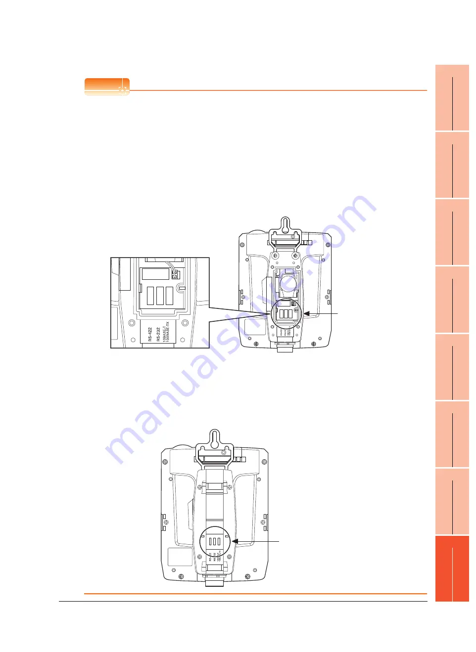
Selection of the RS-232 connection, RS-422 connection, or Ethernet connection
The Handy GOT can be connected to a controller in either of the RS-232 connection, RS-422 connection, or
Ethernet connection.
Select the RS-232 connection, RS-422 connection, or Ethernet connection by using the cable connector for the
PLC communication in the environmental protection back cover.
For the RS-232 connection, connect the PLC communication cable connector with the RS-232 connector.
For the RS-422 connection, connect the PLC communication cable connector with the RS-422 connector.
For the Ethernet connection, connect the PLC communication cable connector with the Ethernet connector.
The available connection type differs depending on the external cable to be used.
GT14H-C
-42P: Ethernet connection
GT11H-C
-37P: RS-232 connection and RS-422 connection
GT11H-C
:
RS-232 connection and RS-422 connection
(The Ethernet connection is selected at factory shipment.)
For switching between the RS-232 connection and RS-422 connection at the Ethernet connection, make sure to
turn off the Handy GOT power before disconnecting or connecting the cable connector for PLC communication in
the environmental protection back cover.
Disconnecting or connecting the cable connector without turning off the Handy GOT power causes a failure. The
selected connection method (RS-232 connection or RS-422 connection) at the Ethernet connection is applied
when the Handy GOT power is turned on.
The connector can be checked through the window when the environmental protection back cover is closed.
It can be used as a method to check the connection type from the outside of the Handy GOT.
Cable connector
for PLC communication
Environmental protection
back cover window
Содержание GT14
Страница 1: ......
Страница 2: ......
Страница 34: ...A 32 ...
Страница 46: ...1 4 1 OVERVIEW 1 1 Features ...
Страница 60: ...3 6 3 SPECIFICATIONS 3 4 Battery specifications ...
Страница 72: ...5 8 5 UL cUL STANDARDS AND EMC DIRECTIVE 5 2 EMC Directive ...
Страница 108: ...6 36 6 OPTION 6 7 With wall mounting Attachment ...
Страница 124: ...8 10 8 COMMUNICATION CABLE 8 2 External Cable Relay Cable ...
Страница 172: ...11 16 11 COMMUNICATION INTERFACE SETTING COMMUNICATION SETTING 11 3 Ethernet Setting ...
Страница 200: ...12 28 12 DISPLAY AND OPERATION SETTINGS GOT SET UP 12 6 License Management ...
Страница 204: ...13 4 13 CLOCK SETTINGS AND BATTERY STATUS DISPLAY TIME SETTING AND DISPLAY 13 1 Time Setting and Display ...
Страница 296: ...14 92 14 FILE DISPLAY AND COPY PROGRAM DATA CONTROL 14 2 Various Data Control ...
Страница 320: ...15 24 15 GOT SELF CHECK DEBUG AND SELF CHECK 15 4 GOT start time ...
Страница 322: ...16 2 16 CLEANING DISPLAY SECTION CLEAN ...
Страница 336: ...17 14 17 INSTALLATION OF COREOS BOOTOS AND STANDARD MONITOR OS 17 5 CoreOS ...
Страница 360: ...19 8 19 MAINTENANCE AND INSPECTION 19 5 Backlight Shutoff Detection ...
Страница 382: ......
Страница 450: ...22 34 22 COMPUTER LINK CONNECTION 22 6 Precautions ...
Страница 508: ...23 58 23 ETHERNET CONNECTION 23 5 Precautions ...
Страница 526: ......
Страница 592: ...26 22 26 SERVO AMPLIFIER CONNECTION 26 7 Precautions ...
Страница 598: ...27 6 27 ROBOT CONTROLLER CONNECTION 27 6 Precautions ...
Страница 607: ...MULTIPLE GOT CONNECTION FUNCTION 29 MULTIPLE GOT CONNECTION FUNCTION 29 1 ...
Страница 608: ......
Страница 619: ...MULTI CHANNEL FUNCTION 30 MULTI CHANNEL FUNCTION 30 1 ...
Страница 620: ......
Страница 635: ...FA TRANSPARENT FUNCTION 31 FA TRANSPARENT FUNCTION 31 1 ...
Страница 636: ......
Страница 688: ...31 52 31 FA TRANSPARENT FUNCTION 31 7 Precautions ...
Страница 698: ...App 10 APPENDICES Appendix 2 Usage Condition of Utility Function ...
Страница 703: ......
Страница 704: ......
Страница 705: ......
Страница 706: ......
Страница 738: ...A 32 ...
Страница 748: ......
Страница 820: ...33 44 33 CONNECTION TO OMRON PLC 33 4 Device Range that Can Be Set ...
Страница 834: ...34 14 34 CONNECTION TO OMRON TEMPERATURE CONTROLLER 34 7 Precautions ...
Страница 912: ...37 22 37 CONNECTION TO JTEKT PLC 37 7 Precautions ...
Страница 930: ...38 18 38 CONNECTION TO SHARP PLC 38 6 Device Range that Can Be Set ...
Страница 980: ...41 16 41 CONNECTION TO TOSHIBA PLC 41 4 Device Range that Can Be Set ...
Страница 996: ...43 8 43 CONNECTION TO PANASONIC SERVO AMPLIFIER 43 7 Precautions ...
Страница 1028: ...44 32 44 CONNECTION TO PANASONIC INDUSTRIAL DEVICES SUNX PLC 44 6 Device Range that Can Be Set ...
Страница 1052: ...46 10 46 CONNECTION TO HITACHI PLC 46 6 Device Range that Can Be Set ...
Страница 1092: ...47 40 47 CONNECTION TO FUJI PLC 47 5 Precautions ...
Страница 1108: ...48 16 48 CONNECTION TO FUJI TEMPERATURE CONTROLLER 48 7 Precautions ...
Страница 1142: ...49 34 49 CONNECTION TO YASKAWA PLC 49 4 Device Range that Can Be Set ...
Страница 1332: ...55 28 55 CONNECTION TO GE PLC 55 7 Precautions ...
Страница 1348: ...56 16 56 CONNECTION TO LS INDUSTRIAL SYSTEMS PLC 56 6 Device Range that Can Be Set ...
Страница 1352: ...57 4 57 CONNECTION TO SICK SAFETY CONTROLLER 57 5 Device Range that Can Be Set ...
Страница 1368: ...58 16 58 CONNECTION TO SIEMENS PLC 58 4 Device Range that Can Be Set ...
Страница 1370: ...59 2 59 CONNECTION TO HIRATA CORPORATION HNC CONTROLLER ...
Страница 1372: ...60 2 60 CONNECTION TO MURATEC CONTROLLER ...
Страница 1373: ...MICROCOMPUTER CONNECTION 61 MICROCOMPUTER CONNECTION SERIAL 61 1 62 MICROCOMPUTER CONNECTION ETHERNET 62 1 ...
Страница 1374: ......
Страница 1515: ...MODBUS CONNECTIONS 63 MODBUS R RTU CONNECTION 63 1 64 MODBUS R TCP CONNECTION 64 1 ...
Страница 1516: ......
Страница 1537: ...CONNECTIONS TO PERIPHERAL EQUIPMENT 65 VNC R SERVER CONNECTION 65 1 ...
Страница 1538: ......
Страница 1545: ......
Страница 1546: ......