


Servicing
5-9
handle it only by its edges. Don’t touch the copper traces! Use anti-static bags and protective
containers to store the board if you won’t reinstall it.
•
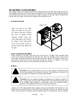
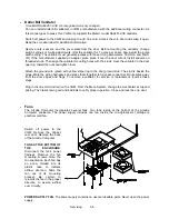
Power Supply
CAUTION:
Replace the power supply
only
with a Midway approved power supply.
Make no substitutions. Otherwise you will void the UL and CE listings on your
video game machine. Non-approved power supplies can pose shock and fire
hazards to players and service personnel.
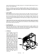
Switch off power to the VGM. Disconnect the line cord. Unlock and remove the rear door. Remove
the back of the Arcade Computer. Unplug the IEC AC power cord. Inside the Arcade Computer,
disconnect DC power cables. These connect to the hard drive, motherboard and other peripherals.
Remove four mounting screws from the outside of the Arcade Computer enclosure. Lift the power
supply out of the cabinet. Before reinstalling the power supply, check the line voltage switch setting.
•
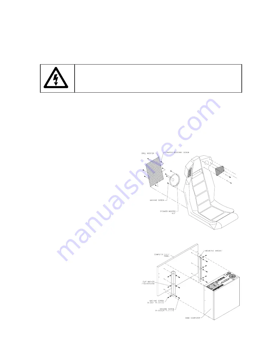
Speakers
This VGM has four speakers. One woofer is
behind a grille at the back of the driver’s seat.
Smaller, full range speakers are behind the
marquee. A second woofer is inside the main
cabinet, accessible from the back. Switch off
power to the VGM.
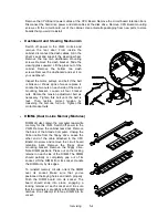
ACCESSING THE SEAT WOOFER.
Remove
mounting screws and set the speaker grille
aside.
Don’t use excess force when removing
or tightening mounting screws threaded into
plastic.
Avoid speaker damage by removing
the upper mounting screws first. (Replace
these top screws last.)
ACCESSING THE CABINET WOOFER.
Unlock and remove the rear door. Unscrew
the Arcade Computer mounting brackets.
Disconnect and remove the Arcade Computer.
Unscrew and remove the computer’s wooden
mounting panel. Remove speaker-mounting
screws.
ACCESSING A MARQUEE SPEAKER.
Unscrew and remove the marquee retainer.
Expose the speakers by removing the
marquee glass. Remove speaker-mounting
screws.
SPEAKER REMOVAL.
Assure proper polarity
by marking each speaker wire (“+” or “Gnd”).
Remove the speaker from the enclosure and
disconnect the wire lugs.
Содержание Offroad Thunder
Страница 3: ...iii...
Страница 4: ...iv...
Страница 15: ...Operation 2 1 2 52 7 81 5 TM 37 5 OPERATION NOTICE The term VGM refers to the video game machine...
Страница 20: ...Operation 2 6 NOTES...
Страница 60: ...Diagnostic Audit Adjustment Menu System 3 40 NOTES...
Страница 63: ...Wiring Circuit Information 4 3 Power Wiring Diagram...
Страница 64: ...Wiring Circuit Information 4 4 Cabinet Wiring Diagram...
Страница 65: ...Wiring Circuit Information 4 5 Player Panel Wiring Diagram...
Страница 71: ...Wiring Circuit Information 4 11 BB12 Audio Amplifier Board Schematic 1 4...
Страница 72: ...Wiring Circuit Information 4 12 BB12 Audio Amplifier Board Schematic 2 4...
Страница 73: ...Wiring Circuit Information 4 13 BB12 Audio Amplifier Board Schematic 3 4...
Страница 74: ...Wiring Circuit Information 4 14 BB12 Audio Amplifier Board Schematic 4 4...
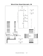
Страница 79: ...Wiring Circuit Information 4 19 Wheel Driver Board Schematic 1 8...
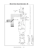
Страница 80: ...Wiring Circuit Information 4 20 Wheel Driver Board Schematic 2 8...
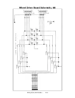
Страница 81: ...Wiring Circuit Information 4 21 Wheel Driver Board Schematic 3 8...
Страница 82: ...Wiring Circuit Information 4 22 Wheel Driver Board Schematic 4 8...
Страница 83: ...Wiring Circuit Information 4 23 Wheel Driver Board Schematic 5 8...
Страница 84: ...Wiring Circuit Information 4 24 Wheel Driver Board Schematic 6 8...
Страница 85: ...Wiring Circuit Information 4 25 Wheel Driver Board Schematic 7 8...
Страница 86: ...Wiring Circuit Information 4 26 Wheel Driver Board Schematic 8 8...
Страница 99: ...Parts 7 3 Cabinet Rear View 01 10714 03 8326...
Страница 100: ...Parts 7 4 Cabinet Joining Details 4700 00033 00B 4701 00005 00 4320 01124 16 04 10112 4020 01100 20...
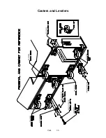
Страница 101: ...Parts 7 5 Casters and Levelers...
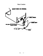
Страница 102: ...Parts 7 6 Rear Casters...
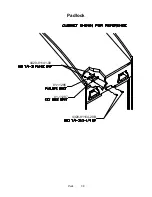
Страница 105: ...Parts 7 9 Padlock 4320 01164 20B 01 11287 01 11286 4420 01141 00...
Страница 106: ...Parts 7 10 Coin Door Assembly See Coin Door Application Table for Assembly Number...
Страница 107: ...Parts 7 11 Pushbutton Assembly 20 9663 XX 20 10129 5 24 8880 24 8828...
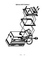
Страница 110: ...Parts 7 14 Optional Bill Validator...
Страница 111: ...Parts 7 15 Cabinet Components...
Страница 113: ...Parts 7 17 Casters and Leg Levelers...
Страница 114: ...Parts 7 18 Throttle Assembly 20 10135 5014 12909 00...
Страница 115: ...Parts 7 19 Fluorescent Lamp Assembly A 22506 20 10444 04 11241 1 24 8809 20 10481 2...
Страница 117: ...Parts 7 21 Arcade Computer Mechanical Components...
Страница 131: ...Parts 7 35 Line Cord Installation Bracket AC Plug Assembly A 23089...
Страница 149: ......


