


Servicing
5-5
•
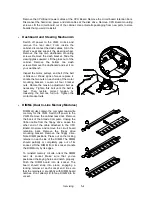
Dollar Bill Validator
(Use MARS AE2451-U3E, UL-recognized currency changer)
You can install dollar bill validators in VGMs manufactured with the additional wiring connector. As
this manual goes to press, this VGM only supports the Mars
model AE2451-U3E validator.
Switch off power to the VGM and unplug the AC line cord. Unlock the coin door and swing it open.
Read the coin door label for additional information.
Remove nuts, spacers, and the cover plate from the door. Before mounting the validator, change
switch settings or make adjustments. (Set the validator for 1 pulse per dollar. Also adjust the pulse
width setting. The validator must generate pulses with these timing parameters: 50mS on and 50mS
off.) If the manufacturer supplied an adapter plate, place it over the door cutout. Install spacers on
threaded studs. Then align the validator mounting holes with the studs. Seat the validator in the door
opening. Install the nuts and tighten them.
Attach the ground wire (green with yellow stripe) lug to the door ground stud. The stud is beside the
hinge. Mate the wiring harnesses and press them together to fully seat connectors. Route wires away
from the door edges and hinge. To remove a validator for service or replacement, reverse these
steps.
Plug in the line cord and turn on the VGM. From the Menu System, change the mechanism setup and
pricing. Then test known good and bad bills to verify proper operation. Close and lock the coin door.
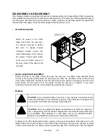
•
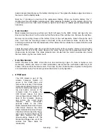
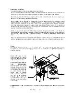
Fans
The Arcade Computer incorporates several fans. Two fans reside at the bottom of the Arcade
Computer enclosure. The power supply includes one fan. Inside the microprocessor cartridge is
another small fan.
Switch off power to the
VGM. Remove the cabinet
rear door. Remove the back
of the Arcade Computer.
FANS AT THE BOTTOM OF
THE ENCLOSURE.
Disconnect the fan’s power
harness. Remove the fan
mounting screws. Note the
fan orientation. Each fan has
an arrow molded into its
plastic case to indicate
airflow direction. Slide the
fan out of its mounting
bracket. Be certain to
reinstall the fan in the proper
direction to assure airflow
over circuitry.
POWER SUPPLY FAN.
The power supply contains no user-serviceable parts. Never open the power
supply.
Содержание Offroad Thunder
Страница 3: ...iii...
Страница 4: ...iv...
Страница 15: ...Operation 2 1 2 52 7 81 5 TM 37 5 OPERATION NOTICE The term VGM refers to the video game machine...
Страница 20: ...Operation 2 6 NOTES...
Страница 60: ...Diagnostic Audit Adjustment Menu System 3 40 NOTES...
Страница 63: ...Wiring Circuit Information 4 3 Power Wiring Diagram...
Страница 64: ...Wiring Circuit Information 4 4 Cabinet Wiring Diagram...
Страница 65: ...Wiring Circuit Information 4 5 Player Panel Wiring Diagram...
Страница 71: ...Wiring Circuit Information 4 11 BB12 Audio Amplifier Board Schematic 1 4...
Страница 72: ...Wiring Circuit Information 4 12 BB12 Audio Amplifier Board Schematic 2 4...
Страница 73: ...Wiring Circuit Information 4 13 BB12 Audio Amplifier Board Schematic 3 4...
Страница 74: ...Wiring Circuit Information 4 14 BB12 Audio Amplifier Board Schematic 4 4...
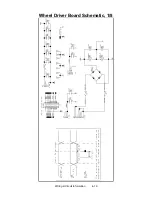
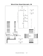
Страница 79: ...Wiring Circuit Information 4 19 Wheel Driver Board Schematic 1 8...
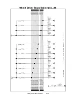
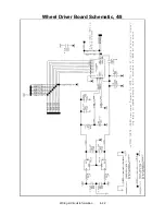
Страница 80: ...Wiring Circuit Information 4 20 Wheel Driver Board Schematic 2 8...
Страница 81: ...Wiring Circuit Information 4 21 Wheel Driver Board Schematic 3 8...
Страница 82: ...Wiring Circuit Information 4 22 Wheel Driver Board Schematic 4 8...
Страница 83: ...Wiring Circuit Information 4 23 Wheel Driver Board Schematic 5 8...
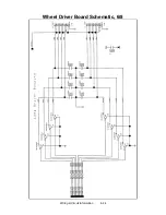
Страница 84: ...Wiring Circuit Information 4 24 Wheel Driver Board Schematic 6 8...
Страница 85: ...Wiring Circuit Information 4 25 Wheel Driver Board Schematic 7 8...
Страница 86: ...Wiring Circuit Information 4 26 Wheel Driver Board Schematic 8 8...
Страница 99: ...Parts 7 3 Cabinet Rear View 01 10714 03 8326...
Страница 100: ...Parts 7 4 Cabinet Joining Details 4700 00033 00B 4701 00005 00 4320 01124 16 04 10112 4020 01100 20...
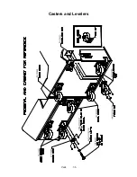
Страница 101: ...Parts 7 5 Casters and Levelers...
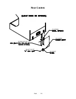
Страница 102: ...Parts 7 6 Rear Casters...
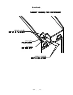
Страница 105: ...Parts 7 9 Padlock 4320 01164 20B 01 11287 01 11286 4420 01141 00...
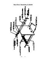
Страница 106: ...Parts 7 10 Coin Door Assembly See Coin Door Application Table for Assembly Number...
Страница 107: ...Parts 7 11 Pushbutton Assembly 20 9663 XX 20 10129 5 24 8880 24 8828...
Страница 110: ...Parts 7 14 Optional Bill Validator...
Страница 111: ...Parts 7 15 Cabinet Components...
Страница 113: ...Parts 7 17 Casters and Leg Levelers...
Страница 114: ...Parts 7 18 Throttle Assembly 20 10135 5014 12909 00...
Страница 115: ...Parts 7 19 Fluorescent Lamp Assembly A 22506 20 10444 04 11241 1 24 8809 20 10481 2...
Страница 117: ...Parts 7 21 Arcade Computer Mechanical Components...
Страница 131: ...Parts 7 35 Line Cord Installation Bracket AC Plug Assembly A 23089...
Страница 149: ......


