Troubleshooting 6-8
Link Troubleshooting Table
SYMPTOM
CAUSE
REQUIRED ACTION
Faulty wiring
1. Don’t extend linking cables that come with VGM.
2. Install required crossover between VGM
cabinets. Each coupler connects two cabinets
(one pair). Don’t use standard telephone type
couplers or wiring to link cabinets.
3. Use only 10 Base-T, Ethernet-type, Category 5,
twisted-pair wiring for VGM data.
•
Can’t connect VGMs (video
game machines) together
Improper linking
hardware
Use required network hub for your local network.
Hub Link Kit permits up to four cabinet
connections. Cabinet array completion requires
basic kit brackets and spacers.
Improper settings
1. Record any error messages that occur during
self-test.
2.
From Operator (Main) Menu, choose
Adjustments Menu. Then select Linked Play
Adjustments Menu. Assure that you’ve set
LINKED PLAY to ON.
3. Be sure that each VGM has unique ID number.
Power problem
If hub is in use, verify that power is applied. AC
adapter wires are thin and easily damaged.
•
VGM
doesn’t recognize
other players in linking
operation
•
VGM functions normally by
itself
Faulty wiring
(3 or more cabinets)
1. Inspect hub indicator lights. Each active port
should have illuminated indicator. If cable
connects, and that position has no lit indicator,
check for cable continuity from hub to cabinet.
2. Assure that no loose wires catch in hinges,
doors, or under cabinet.
3. Verify that linking cable connects to Network
Board at each VGM’s computer.
4. Verify that each linking cable operates properly
by placing it in working VGM.
Improper hub switch
setting
1. Assure that switches on hub are set correctly
according to Hub Link Kit instructions.
(Networked cabinets don’t require couplers. Hub
has electronic crossover.)
2. Inspect hub indicator lights for link activity. See
manufacturer’s literature for diagnostics.
Wrong software
version
Verify that all linked cabinets use same software
version. Otherwise, linked cabinets won’t
recognize each other. Contact your distributor.
Faulty wiring
(2 cabinets)
1. Insert crossover connections between coupled
cabinets. Standard couplers appear identical to
devices supplied with cabinets, but don’t include
internal crossover.
2. Verify that each linking crossover coupler
operates properly by placing it in working link
between two cabinets.
•
Some VGMs in group link
properly, while others don’t
Faulty wiring
(3 or more cabinets)
1. You used additional crossover connector and
cable to extend VGM or hub link connection.
Two crossovers cancel and cause same
problem as no link crossover.
2. Connect cables directly to hub. Don’t use
crossover coupler and hub together in single
network.
3. Separate communications wiring from other
wiring. Wires that must cross should cross at
right angles to limit noise pickup.
Содержание Offroad Thunder
Страница 3: ...iii...
Страница 4: ...iv...
Страница 15: ...Operation 2 1 2 52 7 81 5 TM 37 5 OPERATION NOTICE The term VGM refers to the video game machine...
Страница 20: ...Operation 2 6 NOTES...
Страница 60: ...Diagnostic Audit Adjustment Menu System 3 40 NOTES...
Страница 63: ...Wiring Circuit Information 4 3 Power Wiring Diagram...
Страница 64: ...Wiring Circuit Information 4 4 Cabinet Wiring Diagram...
Страница 65: ...Wiring Circuit Information 4 5 Player Panel Wiring Diagram...
Страница 71: ...Wiring Circuit Information 4 11 BB12 Audio Amplifier Board Schematic 1 4...
Страница 72: ...Wiring Circuit Information 4 12 BB12 Audio Amplifier Board Schematic 2 4...
Страница 73: ...Wiring Circuit Information 4 13 BB12 Audio Amplifier Board Schematic 3 4...
Страница 74: ...Wiring Circuit Information 4 14 BB12 Audio Amplifier Board Schematic 4 4...
Страница 79: ...Wiring Circuit Information 4 19 Wheel Driver Board Schematic 1 8...
Страница 80: ...Wiring Circuit Information 4 20 Wheel Driver Board Schematic 2 8...
Страница 81: ...Wiring Circuit Information 4 21 Wheel Driver Board Schematic 3 8...
Страница 82: ...Wiring Circuit Information 4 22 Wheel Driver Board Schematic 4 8...
Страница 83: ...Wiring Circuit Information 4 23 Wheel Driver Board Schematic 5 8...
Страница 84: ...Wiring Circuit Information 4 24 Wheel Driver Board Schematic 6 8...
Страница 85: ...Wiring Circuit Information 4 25 Wheel Driver Board Schematic 7 8...
Страница 86: ...Wiring Circuit Information 4 26 Wheel Driver Board Schematic 8 8...
Страница 99: ...Parts 7 3 Cabinet Rear View 01 10714 03 8326...
Страница 100: ...Parts 7 4 Cabinet Joining Details 4700 00033 00B 4701 00005 00 4320 01124 16 04 10112 4020 01100 20...
Страница 101: ...Parts 7 5 Casters and Levelers...
Страница 102: ...Parts 7 6 Rear Casters...
Страница 105: ...Parts 7 9 Padlock 4320 01164 20B 01 11287 01 11286 4420 01141 00...
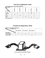
Страница 106: ...Parts 7 10 Coin Door Assembly See Coin Door Application Table for Assembly Number...
Страница 107: ...Parts 7 11 Pushbutton Assembly 20 9663 XX 20 10129 5 24 8880 24 8828...
Страница 110: ...Parts 7 14 Optional Bill Validator...
Страница 111: ...Parts 7 15 Cabinet Components...
Страница 113: ...Parts 7 17 Casters and Leg Levelers...
Страница 114: ...Parts 7 18 Throttle Assembly 20 10135 5014 12909 00...
Страница 115: ...Parts 7 19 Fluorescent Lamp Assembly A 22506 20 10444 04 11241 1 24 8809 20 10481 2...
Страница 117: ...Parts 7 21 Arcade Computer Mechanical Components...
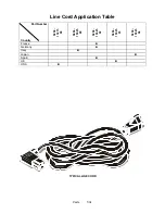
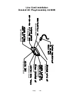
Страница 131: ...Parts 7 35 Line Cord Installation Bracket AC Plug Assembly A 23089...
Страница 149: ......

