


Troubleshooting 6-10
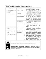
Player Control Troubleshooting Table, continued
SYMPTOM
CAUSE
REQUIRED ACTION
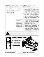
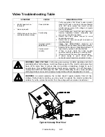
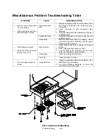
Blocked or faulty fan
With VGM power on, check airflow near each
computer fan. Case cooling fans are intake fans.
Power supply fan is exhaust fan. Assure that
nothing blocks airflow.
Faulty mechanical
parts
Turn off VGM power. Open dashboard. Support
steering wheel and remove outer mounting
screws. Remove metal shield (if your VGM has
one) over motor. Inspect for faulty or worn belts,
bearings, couplings, gears, etc.
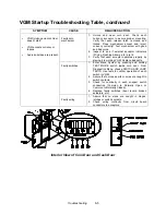
Faulty Wheel Driver
Board
1. Inspect Wheel Driver Board under low-light
conditions. LEDs glow if motor driver circuits
receive AC power from transformer. (Voltages or
signals may or may not be normal.)
2. Examine fuses and cables on Wheel Driver
Board. Replace bad fuses. Using digital
voltmeter, verify AC voltage between each fuse
holder and ground. You should measure
approximately 25V. See Wiring Diagram.
3. Using 20 VAC setting on digital voltmeter,
measure DC voltage at motor. Don’t move
steering wheel, drive belt, or motor while making
this measurement. Any reading indicates
unstable supply that may contain ripple or noise.
4. Verify proper operation of Wheel Driver Board by
placing it in working VGM.
•
Sloppy, unpredictable or
ineffective steering
•
Video appears on screen
•
VGM
(video game machine)
starts normally
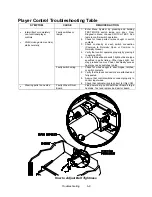
Loose or worn drive
belt
1. Turn off VGM power. Open dashboard. Support
steering wheel and remove outer mounting
screws. Remove metal shield (if your VGM has
one) over motor. Inspect for faulty or worn belts,
bearings, couplings, gears, etc.
2. If drive belt isn’t worn or damaged, check its
tightness.
Improperly set
feedback
1. From Diagnostics Menu, choose FORCE
FEEDBACK ADJUSTMENT.
2. Set feedback to match player requirements.
Maximum force may be too extreme for very
young or inexperienced customers.
Faulty circuit
1. Examine fuses and cables on Wheel Driver
Board.
2. Check cables and wiring between computer,
interface, driver and motor.
3. Check transformer and its connections.
4. Replace bad parts.
•
No wheel feedback
•
Steering aims vehicle as
expected
Faulty motor
1. Turn off VGM power. Open dashboard. Support
steering wheel and remove outer mounting
screws.
2. Remove metal shield (if your VGM has one) over
motor.
3. Unscrew
caps.
4. Inspect motor brushes. Replace worn parts.
Содержание Offroad Thunder
Страница 3: ...iii...
Страница 4: ...iv...
Страница 15: ...Operation 2 1 2 52 7 81 5 TM 37 5 OPERATION NOTICE The term VGM refers to the video game machine...
Страница 20: ...Operation 2 6 NOTES...
Страница 60: ...Diagnostic Audit Adjustment Menu System 3 40 NOTES...
Страница 63: ...Wiring Circuit Information 4 3 Power Wiring Diagram...
Страница 64: ...Wiring Circuit Information 4 4 Cabinet Wiring Diagram...
Страница 65: ...Wiring Circuit Information 4 5 Player Panel Wiring Diagram...
Страница 71: ...Wiring Circuit Information 4 11 BB12 Audio Amplifier Board Schematic 1 4...
Страница 72: ...Wiring Circuit Information 4 12 BB12 Audio Amplifier Board Schematic 2 4...
Страница 73: ...Wiring Circuit Information 4 13 BB12 Audio Amplifier Board Schematic 3 4...
Страница 74: ...Wiring Circuit Information 4 14 BB12 Audio Amplifier Board Schematic 4 4...
Страница 79: ...Wiring Circuit Information 4 19 Wheel Driver Board Schematic 1 8...
Страница 80: ...Wiring Circuit Information 4 20 Wheel Driver Board Schematic 2 8...
Страница 81: ...Wiring Circuit Information 4 21 Wheel Driver Board Schematic 3 8...
Страница 82: ...Wiring Circuit Information 4 22 Wheel Driver Board Schematic 4 8...
Страница 83: ...Wiring Circuit Information 4 23 Wheel Driver Board Schematic 5 8...
Страница 84: ...Wiring Circuit Information 4 24 Wheel Driver Board Schematic 6 8...
Страница 85: ...Wiring Circuit Information 4 25 Wheel Driver Board Schematic 7 8...
Страница 86: ...Wiring Circuit Information 4 26 Wheel Driver Board Schematic 8 8...
Страница 99: ...Parts 7 3 Cabinet Rear View 01 10714 03 8326...
Страница 100: ...Parts 7 4 Cabinet Joining Details 4700 00033 00B 4701 00005 00 4320 01124 16 04 10112 4020 01100 20...
Страница 101: ...Parts 7 5 Casters and Levelers...
Страница 102: ...Parts 7 6 Rear Casters...
Страница 105: ...Parts 7 9 Padlock 4320 01164 20B 01 11287 01 11286 4420 01141 00...
Страница 106: ...Parts 7 10 Coin Door Assembly See Coin Door Application Table for Assembly Number...
Страница 107: ...Parts 7 11 Pushbutton Assembly 20 9663 XX 20 10129 5 24 8880 24 8828...
Страница 110: ...Parts 7 14 Optional Bill Validator...
Страница 111: ...Parts 7 15 Cabinet Components...
Страница 113: ...Parts 7 17 Casters and Leg Levelers...
Страница 114: ...Parts 7 18 Throttle Assembly 20 10135 5014 12909 00...
Страница 115: ...Parts 7 19 Fluorescent Lamp Assembly A 22506 20 10444 04 11241 1 24 8809 20 10481 2...
Страница 117: ...Parts 7 21 Arcade Computer Mechanical Components...
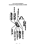
Страница 131: ...Parts 7 35 Line Cord Installation Bracket AC Plug Assembly A 23089...
Страница 149: ......


