Wiring & Circuit Information 4-7
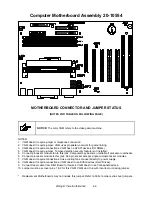
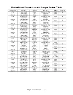
Motherboard Connector and Jumper Status Table
Designation
Location
Function
Meaning
Setting
Default
J1A1
Lower Right
Wake
Not Used In This
Open
Near Board
On
VGM (No
1 & 2
(Note 1)
Expansion Slot
Ring
Telephone)
J1E1
Lower Center
Wake
Not Used In This
Open
Near Board
On
VGM (No
(Note 2)
Expansion Slot
LAN
PC LAN)
J1F2
Lower Center
CD Audio
Not Used In This
Open
Near Board
Input
VGM (No
(Note 3)
Expansion Slot
Circuit
CD Player)
J2F1
Lower Center
CD Data
Not Used In This
Open
Near Board
Input
VGM (No
(Note 3)
Expansion Slot
Circuit
CD Player)
J2F2
Lower Center
Telephony
Not Used In This
Open
Near Board
Input
VGM (No
(Note 1)
Expansion Slot
Circuit
Telephone)
J2F3
Lower Center
Auxiliary
Not Used In This
Open
Near Board
Input
VGM (No
(Note 3)
Expansion Slot
Circuit
Aux Devices)
J3F1
Middle Center
Chassis
Not Used In This
Open
Near CPU
Intrusion
VGM (No
1 & 2
(Note 4)
And Fan
Circuit
Intrusion)
J3F2
Middle Center
Processor
Two Speed Fan
Open
Near CPU
Fan
For Processor
1, 2, & 3
(Note 5)
And Fan
Circuit
Cooling
J4J1
Center Left
System
System
Open
Module With
Micro-
Micro-
Filled
(Note 6)
Fan Assembly
Processor
Processor
J4M1
Center Left
Processor
Controlled Fan
Open
Near CPU
Fan
For Processor
1, 2, & 3
(Note 7)
Module
Circuit
Cooling
J7M1
Upper Left
Case
Controlled Fan
Open
Near Power &
Fan
For Hard Disk
1, 2, & 3
(Note 7)
Floppy Jacks
Circuit
Drive Cooling
J8J1
Upper Left
SCSI
Not Used In This
Open
Between Hard
Drive
VGM (No
1 & 2
(Note 8)
& Floppy Jacks
Indicator
SCSI Drives)
J8FR
Upper Center
Front
Only Reset
Open
Near Hard Disk
Panel
Pins Are Used
1 & 2
(Note 9)
Drive Jacks
Devices
In This VGM
J8A1
Upper Right
Configur-
Starts System
Open
Near Battery
ation
Setup Routine
1 & 2
(Note 10)
And Speaker
Select
or Operation
2 & 3
Содержание Offroad Thunder
Страница 3: ...iii...
Страница 4: ...iv...
Страница 15: ...Operation 2 1 2 52 7 81 5 TM 37 5 OPERATION NOTICE The term VGM refers to the video game machine...
Страница 20: ...Operation 2 6 NOTES...
Страница 60: ...Diagnostic Audit Adjustment Menu System 3 40 NOTES...
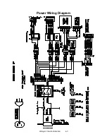
Страница 63: ...Wiring Circuit Information 4 3 Power Wiring Diagram...
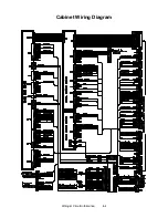
Страница 64: ...Wiring Circuit Information 4 4 Cabinet Wiring Diagram...
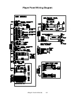
Страница 65: ...Wiring Circuit Information 4 5 Player Panel Wiring Diagram...
Страница 71: ...Wiring Circuit Information 4 11 BB12 Audio Amplifier Board Schematic 1 4...
Страница 72: ...Wiring Circuit Information 4 12 BB12 Audio Amplifier Board Schematic 2 4...
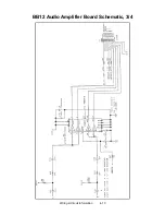
Страница 73: ...Wiring Circuit Information 4 13 BB12 Audio Amplifier Board Schematic 3 4...
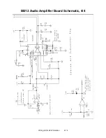
Страница 74: ...Wiring Circuit Information 4 14 BB12 Audio Amplifier Board Schematic 4 4...
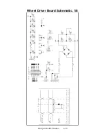
Страница 79: ...Wiring Circuit Information 4 19 Wheel Driver Board Schematic 1 8...
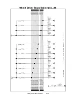
Страница 80: ...Wiring Circuit Information 4 20 Wheel Driver Board Schematic 2 8...
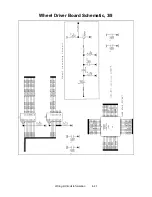
Страница 81: ...Wiring Circuit Information 4 21 Wheel Driver Board Schematic 3 8...
Страница 82: ...Wiring Circuit Information 4 22 Wheel Driver Board Schematic 4 8...
Страница 83: ...Wiring Circuit Information 4 23 Wheel Driver Board Schematic 5 8...
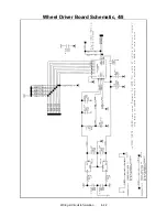
Страница 84: ...Wiring Circuit Information 4 24 Wheel Driver Board Schematic 6 8...
Страница 85: ...Wiring Circuit Information 4 25 Wheel Driver Board Schematic 7 8...
Страница 86: ...Wiring Circuit Information 4 26 Wheel Driver Board Schematic 8 8...
Страница 99: ...Parts 7 3 Cabinet Rear View 01 10714 03 8326...
Страница 100: ...Parts 7 4 Cabinet Joining Details 4700 00033 00B 4701 00005 00 4320 01124 16 04 10112 4020 01100 20...
Страница 101: ...Parts 7 5 Casters and Levelers...
Страница 102: ...Parts 7 6 Rear Casters...
Страница 105: ...Parts 7 9 Padlock 4320 01164 20B 01 11287 01 11286 4420 01141 00...
Страница 106: ...Parts 7 10 Coin Door Assembly See Coin Door Application Table for Assembly Number...
Страница 107: ...Parts 7 11 Pushbutton Assembly 20 9663 XX 20 10129 5 24 8880 24 8828...
Страница 110: ...Parts 7 14 Optional Bill Validator...
Страница 111: ...Parts 7 15 Cabinet Components...
Страница 113: ...Parts 7 17 Casters and Leg Levelers...
Страница 114: ...Parts 7 18 Throttle Assembly 20 10135 5014 12909 00...
Страница 115: ...Parts 7 19 Fluorescent Lamp Assembly A 22506 20 10444 04 11241 1 24 8809 20 10481 2...
Страница 117: ...Parts 7 21 Arcade Computer Mechanical Components...
Страница 131: ...Parts 7 35 Line Cord Installation Bracket AC Plug Assembly A 23089...
Страница 149: ......


