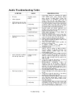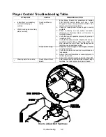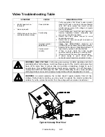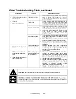
Troubleshooting 6-1
2
))52$'
7+81'(5
TM
&+$37(5
TROUBLESHOOTING
NOTICE: The term VGM refers to the video game machine.
CAUTION: This VGM uses complex electronic components that are very sensitive to
static electricity. Observe the following precautions before handling VGM electronics.
Failure to do so may void your warranty and could damage electronic assemblies.
•
Before servicing electronics, turn off AC power to the VGM. Wait for capacitors to discharge.
•
Before touching or handling electronic assemblies, discharge static electricity on your body. To
discharge this static, begin by connecting the line cord to a grounded outlet. Don’t turn on the
VGM! Next, touch the safety ground stud of the power supply chassis.
•
Store electronic assemblies in an anti-static area. Use anti-static bags to store or transport VGM
circuit boards. Transport the hard drive in its shipping container.
•
Don’t remove or connect electronic assemblies when cabinet power is on. Otherwise, you’ll
damage electronic assemblies and void the VGM warranty.
•
After you complete maintenance or service, replace ground wires, shields, safety covers, etc.
Install and tighten ground and mounting screws.
Содержание Offroad Thunder
Страница 3: ...iii...
Страница 4: ...iv...
Страница 15: ...Operation 2 1 2 52 7 81 5 TM 37 5 OPERATION NOTICE The term VGM refers to the video game machine...
Страница 20: ...Operation 2 6 NOTES...
Страница 60: ...Diagnostic Audit Adjustment Menu System 3 40 NOTES...
Страница 63: ...Wiring Circuit Information 4 3 Power Wiring Diagram...
Страница 64: ...Wiring Circuit Information 4 4 Cabinet Wiring Diagram...
Страница 65: ...Wiring Circuit Information 4 5 Player Panel Wiring Diagram...
Страница 71: ...Wiring Circuit Information 4 11 BB12 Audio Amplifier Board Schematic 1 4...
Страница 72: ...Wiring Circuit Information 4 12 BB12 Audio Amplifier Board Schematic 2 4...
Страница 73: ...Wiring Circuit Information 4 13 BB12 Audio Amplifier Board Schematic 3 4...
Страница 74: ...Wiring Circuit Information 4 14 BB12 Audio Amplifier Board Schematic 4 4...
Страница 79: ...Wiring Circuit Information 4 19 Wheel Driver Board Schematic 1 8...
Страница 80: ...Wiring Circuit Information 4 20 Wheel Driver Board Schematic 2 8...
Страница 81: ...Wiring Circuit Information 4 21 Wheel Driver Board Schematic 3 8...
Страница 82: ...Wiring Circuit Information 4 22 Wheel Driver Board Schematic 4 8...
Страница 83: ...Wiring Circuit Information 4 23 Wheel Driver Board Schematic 5 8...
Страница 84: ...Wiring Circuit Information 4 24 Wheel Driver Board Schematic 6 8...
Страница 85: ...Wiring Circuit Information 4 25 Wheel Driver Board Schematic 7 8...
Страница 86: ...Wiring Circuit Information 4 26 Wheel Driver Board Schematic 8 8...
Страница 99: ...Parts 7 3 Cabinet Rear View 01 10714 03 8326...
Страница 100: ...Parts 7 4 Cabinet Joining Details 4700 00033 00B 4701 00005 00 4320 01124 16 04 10112 4020 01100 20...
Страница 101: ...Parts 7 5 Casters and Levelers...
Страница 102: ...Parts 7 6 Rear Casters...
Страница 105: ...Parts 7 9 Padlock 4320 01164 20B 01 11287 01 11286 4420 01141 00...
Страница 106: ...Parts 7 10 Coin Door Assembly See Coin Door Application Table for Assembly Number...
Страница 107: ...Parts 7 11 Pushbutton Assembly 20 9663 XX 20 10129 5 24 8880 24 8828...
Страница 110: ...Parts 7 14 Optional Bill Validator...
Страница 111: ...Parts 7 15 Cabinet Components...
Страница 113: ...Parts 7 17 Casters and Leg Levelers...
Страница 114: ...Parts 7 18 Throttle Assembly 20 10135 5014 12909 00...
Страница 115: ...Parts 7 19 Fluorescent Lamp Assembly A 22506 20 10444 04 11241 1 24 8809 20 10481 2...
Страница 117: ...Parts 7 21 Arcade Computer Mechanical Components...
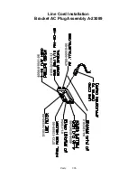
Страница 131: ...Parts 7 35 Line Cord Installation Bracket AC Plug Assembly A 23089...
Страница 149: ......


