Operation 2-5
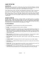
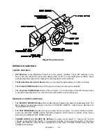
engine RPM. A top-right gauge measures remaining nitro fuel. At the screen’s top-center, a digital clock
times the current lap in seconds. As appropriate, the screen also flashes CHECKPOINT.
DISPLAYS
The player’s vehicle appears at the center of the screen. The numbers floating above some vehicles
indicate that other humans control them. (These are linked players.) The Arcade Computer controls trucks
without numbers. At the bottom of the screen, another instrument displays relative positions of nearby
trucks. The right side of the screen provides race statistics…
•
Position per number of trucks (for example, “11
th
/ 12”)
•
The number of cars ahead of the player (“9 cars ahead”)
•
A lap timer for each lap (“0:2:00”)
•
Score box (only during scored game modes)
GAME ACTION
Action begins after the “three-two-one” countdown. The announcer hollers “Go!” To continue play, the
player must drive past each checkpoint within the time limit. To decrease time between checkpoints,
players must avoid fixed obstacles and other trucks. Ramps allow players to advance more quickly, collect
hovering nitro icons, or avoid obstacles. (Red nitro icons contain more fuel than blue nitro icons.)
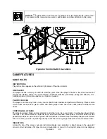
Players can change their view of the action by pressing the view buttons. These buttons are on the left
side of the control panel. Game sounds include announcer comments, engine noise, and other effects.
SCORING
Players who set a speed record may enter their initials in the High Score Table. After a player completes a
certain number of courses, he can choose additional courses. (Adjustments determine the number.)
HEAD-TO-HEAD RACING
Networked cabinets offer players linked, head-to-head racing competition. Each player begins the course-
selection process. A join-in message alerts subsequent players to the possibility of a linked race. If players
don't begin their selection process before this message disappears, their races don't link. (Unlinked
players compete in independent races, as usual.) Players may use the solo feature to decline a link.
If other players begin selection during the join-in message, the cabinets communicate over the network.
Each additional cabinet sends out its own packet containing a unique unit ID. In return, each cabinet
receives data from active cabinets. A "waiting" message indicates that other players are still selecting race
options. Eventually, the last player finishes selecting or the waiting period ends. At this point, all linked
players see the start screen simultaneously.
Latecomers can't participate in an ongoing linked race. They can begin an independent race. The link
automatically terminates when the game is over. Players can then set up another link.
MAINTENANCE
•
Cabinet and Seat
Use plastic-safe, non-abrasive cleaners to avoid damage. Apply cleaner to a clean cloth or sponge.
Use this to wipe the seat or cabinet. Don’t apply cleaner directly to the artwork or cabinet!
•
Player Controls
Use plastic-safe non-abrasive cleaners to avoid damage. Apply cleaner to a clean cloth or sponge.
Use this to wipe the player controls. Don’t apply the cleaner directly to the controls!
•
Viewing Glass
To clean the glass, you don’t need to switch off power to the game. Apply a mild glass cleaner to a
clean cloth or sponge. Use this to wipe the viewing glass. Don’t apply the cleaner directly to the glass!
Liquid could drip down into switch or motor circuits and cause erratic game operation.
Содержание Offroad Thunder
Страница 3: ...iii...
Страница 4: ...iv...
Страница 15: ...Operation 2 1 2 52 7 81 5 TM 37 5 OPERATION NOTICE The term VGM refers to the video game machine...
Страница 20: ...Operation 2 6 NOTES...
Страница 60: ...Diagnostic Audit Adjustment Menu System 3 40 NOTES...
Страница 63: ...Wiring Circuit Information 4 3 Power Wiring Diagram...
Страница 64: ...Wiring Circuit Information 4 4 Cabinet Wiring Diagram...
Страница 65: ...Wiring Circuit Information 4 5 Player Panel Wiring Diagram...
Страница 71: ...Wiring Circuit Information 4 11 BB12 Audio Amplifier Board Schematic 1 4...
Страница 72: ...Wiring Circuit Information 4 12 BB12 Audio Amplifier Board Schematic 2 4...
Страница 73: ...Wiring Circuit Information 4 13 BB12 Audio Amplifier Board Schematic 3 4...
Страница 74: ...Wiring Circuit Information 4 14 BB12 Audio Amplifier Board Schematic 4 4...
Страница 79: ...Wiring Circuit Information 4 19 Wheel Driver Board Schematic 1 8...
Страница 80: ...Wiring Circuit Information 4 20 Wheel Driver Board Schematic 2 8...
Страница 81: ...Wiring Circuit Information 4 21 Wheel Driver Board Schematic 3 8...
Страница 82: ...Wiring Circuit Information 4 22 Wheel Driver Board Schematic 4 8...
Страница 83: ...Wiring Circuit Information 4 23 Wheel Driver Board Schematic 5 8...
Страница 84: ...Wiring Circuit Information 4 24 Wheel Driver Board Schematic 6 8...
Страница 85: ...Wiring Circuit Information 4 25 Wheel Driver Board Schematic 7 8...
Страница 86: ...Wiring Circuit Information 4 26 Wheel Driver Board Schematic 8 8...
Страница 99: ...Parts 7 3 Cabinet Rear View 01 10714 03 8326...
Страница 100: ...Parts 7 4 Cabinet Joining Details 4700 00033 00B 4701 00005 00 4320 01124 16 04 10112 4020 01100 20...
Страница 101: ...Parts 7 5 Casters and Levelers...
Страница 102: ...Parts 7 6 Rear Casters...
Страница 105: ...Parts 7 9 Padlock 4320 01164 20B 01 11287 01 11286 4420 01141 00...
Страница 106: ...Parts 7 10 Coin Door Assembly See Coin Door Application Table for Assembly Number...
Страница 107: ...Parts 7 11 Pushbutton Assembly 20 9663 XX 20 10129 5 24 8880 24 8828...
Страница 110: ...Parts 7 14 Optional Bill Validator...
Страница 111: ...Parts 7 15 Cabinet Components...
Страница 113: ...Parts 7 17 Casters and Leg Levelers...
Страница 114: ...Parts 7 18 Throttle Assembly 20 10135 5014 12909 00...
Страница 115: ...Parts 7 19 Fluorescent Lamp Assembly A 22506 20 10444 04 11241 1 24 8809 20 10481 2...
Страница 117: ...Parts 7 21 Arcade Computer Mechanical Components...
Страница 131: ...Parts 7 35 Line Cord Installation Bracket AC Plug Assembly A 23089...
Страница 149: ......

