


1-6
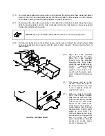
[ ] 10. To protect seat pedestal mounting rails during shipment, the factory bolts them inside the cabinet.
Remove the 1/4-20 hex-head bolts that secure the rails. Slide the rails partway out of the bottom-
front cabinet opening. (See the nearby diagram for proper placement.)
[ ] 11. Fasten down the rails in this new position. Firmly tighten the rail bolts, but don’t torque them down.
Slide the seat pedestal onto the rails. Vertically position the rails. Remove the seat pedestal.
Tighten the rail bolts with a wrench.
NOTICE: When you install the seat pedestal, take care to avoid pinching wires!
[ ] 12. Roll the seat pedestal near the cabinet. Leave enough space to attach the wiring harness. Mate
each seat pedestal cable connector with its cabinet cable connector. Press connectors firmly to
seat contacts.
[
]
13. Align the seat pedestal
opening with the rail ends.
Slide the seat pedestal
forward onto the extended
mounting rails. Align holes.
Attach the seat pedestal using
1/4-20, tamper-resistant
screws and large flat
washers. You’ll find a T27
wrench with the spare parts.
Use it to tighten these screws
firmly.
INSTALL THE LINE CORD
[
]
14. The power cord is in the
cashbox. Match the holes on
the IEC plug with the prongs
in the receptacle. Push the
plug firmly to seat it.
[ ] 15. Before you plug in the VGM,
verify line voltage compati-
bility with the machine. Then
plug the VGM into a grounded
(3-terminal) AC wall outlet.
Switch on the VGM at the
on/off switch. (This switch is
on the cabinet roof. Face the
cabinet’s back. Find the on/off
switch to your right.) The
VGM will power up and begin
self-diagnostics. If diagnostics
find no errors, the VGM
enters Attract Mode. (Racing
scenes and sounds, player
scores, messages, etc.)
Содержание Offroad Thunder
Страница 3: ...iii...
Страница 4: ...iv...
Страница 15: ...Operation 2 1 2 52 7 81 5 TM 37 5 OPERATION NOTICE The term VGM refers to the video game machine...
Страница 20: ...Operation 2 6 NOTES...
Страница 60: ...Diagnostic Audit Adjustment Menu System 3 40 NOTES...
Страница 63: ...Wiring Circuit Information 4 3 Power Wiring Diagram...
Страница 64: ...Wiring Circuit Information 4 4 Cabinet Wiring Diagram...
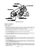
Страница 65: ...Wiring Circuit Information 4 5 Player Panel Wiring Diagram...
Страница 71: ...Wiring Circuit Information 4 11 BB12 Audio Amplifier Board Schematic 1 4...
Страница 72: ...Wiring Circuit Information 4 12 BB12 Audio Amplifier Board Schematic 2 4...
Страница 73: ...Wiring Circuit Information 4 13 BB12 Audio Amplifier Board Schematic 3 4...
Страница 74: ...Wiring Circuit Information 4 14 BB12 Audio Amplifier Board Schematic 4 4...
Страница 79: ...Wiring Circuit Information 4 19 Wheel Driver Board Schematic 1 8...
Страница 80: ...Wiring Circuit Information 4 20 Wheel Driver Board Schematic 2 8...
Страница 81: ...Wiring Circuit Information 4 21 Wheel Driver Board Schematic 3 8...
Страница 82: ...Wiring Circuit Information 4 22 Wheel Driver Board Schematic 4 8...
Страница 83: ...Wiring Circuit Information 4 23 Wheel Driver Board Schematic 5 8...
Страница 84: ...Wiring Circuit Information 4 24 Wheel Driver Board Schematic 6 8...
Страница 85: ...Wiring Circuit Information 4 25 Wheel Driver Board Schematic 7 8...
Страница 86: ...Wiring Circuit Information 4 26 Wheel Driver Board Schematic 8 8...
Страница 99: ...Parts 7 3 Cabinet Rear View 01 10714 03 8326...
Страница 100: ...Parts 7 4 Cabinet Joining Details 4700 00033 00B 4701 00005 00 4320 01124 16 04 10112 4020 01100 20...
Страница 101: ...Parts 7 5 Casters and Levelers...
Страница 102: ...Parts 7 6 Rear Casters...
Страница 105: ...Parts 7 9 Padlock 4320 01164 20B 01 11287 01 11286 4420 01141 00...
Страница 106: ...Parts 7 10 Coin Door Assembly See Coin Door Application Table for Assembly Number...
Страница 107: ...Parts 7 11 Pushbutton Assembly 20 9663 XX 20 10129 5 24 8880 24 8828...
Страница 110: ...Parts 7 14 Optional Bill Validator...
Страница 111: ...Parts 7 15 Cabinet Components...
Страница 113: ...Parts 7 17 Casters and Leg Levelers...
Страница 114: ...Parts 7 18 Throttle Assembly 20 10135 5014 12909 00...
Страница 115: ...Parts 7 19 Fluorescent Lamp Assembly A 22506 20 10444 04 11241 1 24 8809 20 10481 2...
Страница 117: ...Parts 7 21 Arcade Computer Mechanical Components...
Страница 131: ...Parts 7 35 Line Cord Installation Bracket AC Plug Assembly A 23089...
Страница 149: ......


