


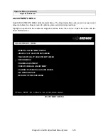


Diagnostic, Audit & Adjustment Menu System 3-8
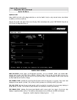
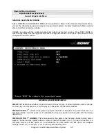
Yellow, Magenta, Cyan.) Set controls as follows: 1. Adjust BRIGHTNESS and CONTRAST to minimum. 2.
Turn up BRIGHTNESS until the pixels in the black stripe begin to glow (turn dark gray). 3. Bring up the
CONTRAST control until you can see 15 bars. Then increase the contrast until you can’t distinguish a
difference between the top two bars.
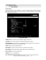
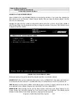
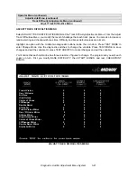
Crosshatch Patterns consist of an on-screen grid and a series of dots. Crosshatch Patterns help you to
check or adjust several monitor parameters: These parameters include convergence, linearity, active
viewing area and dynamic focus. The grid and the dots should be all white in color, with no fringes or
parallel images. The lines should be straight and the dots round. For more detail on these adjustments,
consult service literature from the monitor manufacturer.
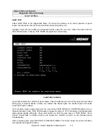
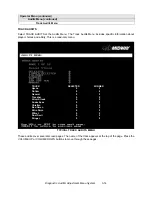
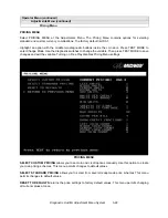
Color Screen tests fill the screen with 100% of the chosen color at normal intensity. The Color Screen
tests help you to check or adjust monitor intensity, black level, blanking and color purity. Each screen
should be absolutely uniform from top to bottom and side to side. No retrace lines or noise should be
visible. Color Screens may not hold their uniformity if the monitor degaussing circuit is defective.
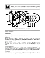
If tests indicate a need for adjustment, use controls on the Monitor Remote Adjustment Board. You can
make other adjustments from the back of the monitor.
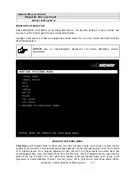
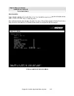
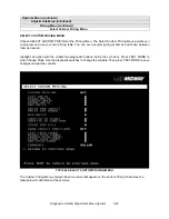
White, Gray, and Black Screens fill the screen with black, gray or white at various intensities. These
monochrome screens help you to check or adjust monitor convergence, purity, contrast and intensity.
These screens also simplify black level and color gun control settings. The screens should be uniform with
no color tints or distortion. No retrace lines or noise should be visible.
If tests indicate a need for adjustment, use controls on the Monitor Remote Adjustment Board.
Содержание Offroad Thunder
Страница 3: ...iii...
Страница 4: ...iv...
Страница 15: ...Operation 2 1 2 52 7 81 5 TM 37 5 OPERATION NOTICE The term VGM refers to the video game machine...
Страница 20: ...Operation 2 6 NOTES...
Страница 60: ...Diagnostic Audit Adjustment Menu System 3 40 NOTES...
Страница 63: ...Wiring Circuit Information 4 3 Power Wiring Diagram...
Страница 64: ...Wiring Circuit Information 4 4 Cabinet Wiring Diagram...
Страница 65: ...Wiring Circuit Information 4 5 Player Panel Wiring Diagram...
Страница 71: ...Wiring Circuit Information 4 11 BB12 Audio Amplifier Board Schematic 1 4...
Страница 72: ...Wiring Circuit Information 4 12 BB12 Audio Amplifier Board Schematic 2 4...
Страница 73: ...Wiring Circuit Information 4 13 BB12 Audio Amplifier Board Schematic 3 4...
Страница 74: ...Wiring Circuit Information 4 14 BB12 Audio Amplifier Board Schematic 4 4...
Страница 79: ...Wiring Circuit Information 4 19 Wheel Driver Board Schematic 1 8...
Страница 80: ...Wiring Circuit Information 4 20 Wheel Driver Board Schematic 2 8...
Страница 81: ...Wiring Circuit Information 4 21 Wheel Driver Board Schematic 3 8...
Страница 82: ...Wiring Circuit Information 4 22 Wheel Driver Board Schematic 4 8...
Страница 83: ...Wiring Circuit Information 4 23 Wheel Driver Board Schematic 5 8...
Страница 84: ...Wiring Circuit Information 4 24 Wheel Driver Board Schematic 6 8...
Страница 85: ...Wiring Circuit Information 4 25 Wheel Driver Board Schematic 7 8...
Страница 86: ...Wiring Circuit Information 4 26 Wheel Driver Board Schematic 8 8...
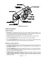
Страница 99: ...Parts 7 3 Cabinet Rear View 01 10714 03 8326...
Страница 100: ...Parts 7 4 Cabinet Joining Details 4700 00033 00B 4701 00005 00 4320 01124 16 04 10112 4020 01100 20...
Страница 101: ...Parts 7 5 Casters and Levelers...
Страница 102: ...Parts 7 6 Rear Casters...
Страница 105: ...Parts 7 9 Padlock 4320 01164 20B 01 11287 01 11286 4420 01141 00...
Страница 106: ...Parts 7 10 Coin Door Assembly See Coin Door Application Table for Assembly Number...
Страница 107: ...Parts 7 11 Pushbutton Assembly 20 9663 XX 20 10129 5 24 8880 24 8828...
Страница 110: ...Parts 7 14 Optional Bill Validator...
Страница 111: ...Parts 7 15 Cabinet Components...
Страница 113: ...Parts 7 17 Casters and Leg Levelers...
Страница 114: ...Parts 7 18 Throttle Assembly 20 10135 5014 12909 00...
Страница 115: ...Parts 7 19 Fluorescent Lamp Assembly A 22506 20 10444 04 11241 1 24 8809 20 10481 2...
Страница 117: ...Parts 7 21 Arcade Computer Mechanical Components...
Страница 131: ...Parts 7 35 Line Cord Installation Bracket AC Plug Assembly A 23089...
Страница 149: ......


