


Diagnostic, Audit & Adjustment Menu System 3-32
Operator Menu (continued)
Adjustments Menu (continued)
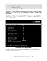
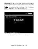
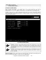
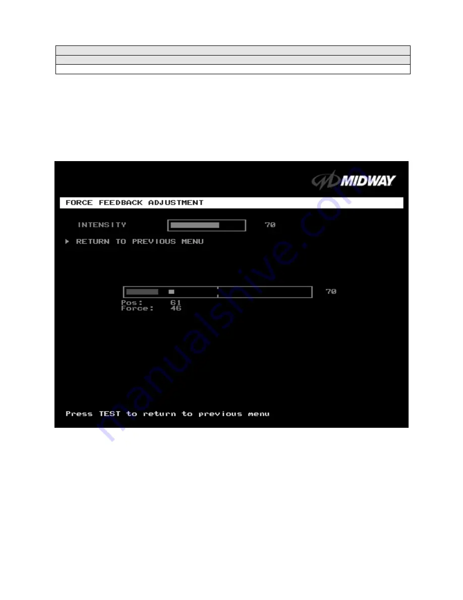
Force Feedback Adjustment Menu
FORCE FEEDBACK ADJUSTMENT
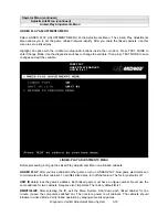
Select FORCE FEEDBACK ADJUSTMENT MENU at the Adjustments Menu. The Force Feedback
Adjustment Menu allows you to alter the intensity of steering wheel feedback.
Highlight an option with the middle two diagnostic buttons inside the coin door. Press TEST MODE to
enter Change Mode. Use the diagnostic switches to change the variable. Then press TEST MODE to save
changes and exit the variable.
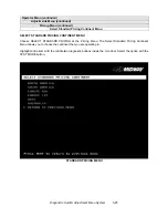
FORCE FEEDBACK ADJUSTMENT MENU
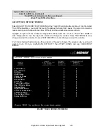
THE INTENSITY ADJUSTMENT ranges from 0% (minimum) to 100% (maximum). The factory default
setting is 60%. If players have superior upper body strength, apply greater force. Younger players may be
more comfortable with smaller force settings.
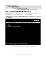
THE FORCE FEEDBACK CENTER TEST checks operation of steering wheel motor drive circuits. Select
this option and move the steering wheel to any position. As soon as you release the wheel, it must
automatically return to its center position. If it doesn’t, then the vehicle won’t respond properly.
Содержание Offroad Thunder
Страница 3: ...iii...
Страница 4: ...iv...
Страница 15: ...Operation 2 1 2 52 7 81 5 TM 37 5 OPERATION NOTICE The term VGM refers to the video game machine...
Страница 20: ...Operation 2 6 NOTES...
Страница 60: ...Diagnostic Audit Adjustment Menu System 3 40 NOTES...
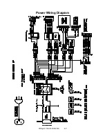
Страница 63: ...Wiring Circuit Information 4 3 Power Wiring Diagram...
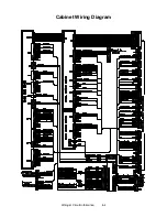
Страница 64: ...Wiring Circuit Information 4 4 Cabinet Wiring Diagram...
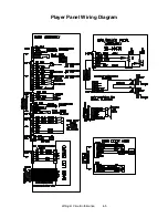
Страница 65: ...Wiring Circuit Information 4 5 Player Panel Wiring Diagram...
Страница 71: ...Wiring Circuit Information 4 11 BB12 Audio Amplifier Board Schematic 1 4...
Страница 72: ...Wiring Circuit Information 4 12 BB12 Audio Amplifier Board Schematic 2 4...
Страница 73: ...Wiring Circuit Information 4 13 BB12 Audio Amplifier Board Schematic 3 4...
Страница 74: ...Wiring Circuit Information 4 14 BB12 Audio Amplifier Board Schematic 4 4...
Страница 79: ...Wiring Circuit Information 4 19 Wheel Driver Board Schematic 1 8...
Страница 80: ...Wiring Circuit Information 4 20 Wheel Driver Board Schematic 2 8...
Страница 81: ...Wiring Circuit Information 4 21 Wheel Driver Board Schematic 3 8...
Страница 82: ...Wiring Circuit Information 4 22 Wheel Driver Board Schematic 4 8...
Страница 83: ...Wiring Circuit Information 4 23 Wheel Driver Board Schematic 5 8...
Страница 84: ...Wiring Circuit Information 4 24 Wheel Driver Board Schematic 6 8...
Страница 85: ...Wiring Circuit Information 4 25 Wheel Driver Board Schematic 7 8...
Страница 86: ...Wiring Circuit Information 4 26 Wheel Driver Board Schematic 8 8...
Страница 99: ...Parts 7 3 Cabinet Rear View 01 10714 03 8326...
Страница 100: ...Parts 7 4 Cabinet Joining Details 4700 00033 00B 4701 00005 00 4320 01124 16 04 10112 4020 01100 20...
Страница 101: ...Parts 7 5 Casters and Levelers...
Страница 102: ...Parts 7 6 Rear Casters...
Страница 105: ...Parts 7 9 Padlock 4320 01164 20B 01 11287 01 11286 4420 01141 00...
Страница 106: ...Parts 7 10 Coin Door Assembly See Coin Door Application Table for Assembly Number...
Страница 107: ...Parts 7 11 Pushbutton Assembly 20 9663 XX 20 10129 5 24 8880 24 8828...
Страница 110: ...Parts 7 14 Optional Bill Validator...
Страница 111: ...Parts 7 15 Cabinet Components...
Страница 113: ...Parts 7 17 Casters and Leg Levelers...
Страница 114: ...Parts 7 18 Throttle Assembly 20 10135 5014 12909 00...
Страница 115: ...Parts 7 19 Fluorescent Lamp Assembly A 22506 20 10444 04 11241 1 24 8809 20 10481 2...
Страница 117: ...Parts 7 21 Arcade Computer Mechanical Components...
Страница 131: ...Parts 7 35 Line Cord Installation Bracket AC Plug Assembly A 23089...
Страница 149: ......


