


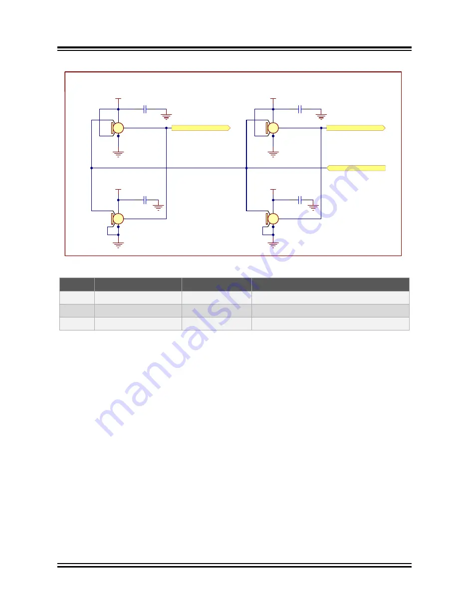
Figure 3-45. QUAD MEMS Microphones Schematic
VDD_3V3
VDD_3V3
GND
GND
0.1uF
10V
0402
C233
0.1uF
10V
0402
C236
GND
GND
VDD_3V3
VDD_3V3
GND
GND
0.1uF
10V
0402
C232
0.1uF
10V
0402
C235
GND
GND
PDMC0_DS0_PD23
PDMC0_DS1_PD24
SPK0641HT4H-1
V
G
1
3
5
4
2
S
C
D
6 7 8
MIC1
SPK0641HT4H-1
V
G
1
3
5
4
2
S
C
D
6 7 8
MIC2
SPK0641HT4H-1
V
G
1
3
5
4
2
S
C
D
6 7 8
MIC3
SPK0641HT4H-1
V
G
1
3
5
4
2
S
C
D
6 7 8
MIC4
4x PDM Microphones
PDMC0_CLK_PD22
Table 3-37. Digital MEMS Signal Descriptions
PIO
Signal Name
Shared With
Signal Description
PD22
PDMC0_CLK_PD22
Ethernet 10/100
PDM clock line for all microphones
PD23
PDMC0_DS0_PD23
Ethernet 10/100
PDM data line 0 (data from MIC1 and MIC2)
PD24
PDMC0_DS1_PD24
Ethernet 10/100
PDM data line 1 (data from MIC3 and MIC4)
Note:
To activate the PDM interface, place the jumper JP2 on the connector J3 as defined in
. In
this mode, the Ethernet 10/100 interface is not accessible.
3.4.9
Wi-Fi/Bluetooth Module (Optional)
The user has the option to solder an ATWILC3000-MR110CA Wi-Fi/BT module with a chip antenna or an
ATWILC3000-MR110UA Wi-Fi/BT module with a U.FL connector.
The ATWILC3000-MR110PA WLAN PHY is designed to achieve a reliable and power-efficient physical layer
communication as specified by IEEE
®
802.11 b/g/n in Single Stream mode with a 20-MHz bandwidth. Advanced
algorithms are used to achieve maximum throughput in a real-world communication environment with impairments
and interference. The PHY implements all required functions such as FFT, filtering, FEC (Viterbi decoder), frequency
and timing acquisition and tracking, channel estimation and equalization, carrier sensing and clear channel
assessment, as well as automatic gain control. The module is available in a fully certified, 22.428 x 17.732 mm,
36-pin module package. For more information about the ATWILC3000, refer to the product
SAMA7G54-EK
Function Blocks
©
2022 Microchip Technology Inc.
and its subsidiaries
User Guide
DS50003273A-page 54


