FUEL INJECTION DESCRIPTIONS AND SYSTEM OPERATION
SERVICE MANUAL NUMBER 24
Page 5D-34
90-861327 OCTOBER 1999
IDLE AIR CONTROL (IAC) VALVE
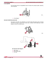
The purpose of the IAC valve assembly is to control engine idle speed, while preventing
stalls due to changes in engine load. The IAC valve, mounted in the throttle body, controls
bypass air around the throttle valves.
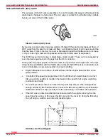
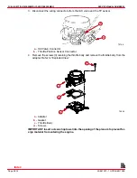
72800
Idle Air Control (IAC) Valve
By moving a conical valve known as a pintle, IN, toward the seat (to decrease air flow), or
OUT, away from the seat (to increase air flow), a controlled amount of air moves around the
throttle valve. If rpm is too low, more air is bypassed around the throttle valve to increase
it. If rpm is too high, less air is bypassed around the throttle valve to decrease it.
The ECM moves the IAC valve in small steps, called counts. These can be measured by
scan tool test equipment, which plugs into the DLC connector.
During idle, the proper position of the IAC valve is engine load, and engine rpm. If the rpm
drops below specification and the throttle valve is closed, the ECM senses a near stall condi-
tion and calculates a new valve position to prevent stalling.
•
Engine idle speed is a function of total air flow into the engine based on IAC valve
pintle position.
•
“Controlled” idle speed is programmed into the ECM, which determines the correct
IAC valve pintle position to maintain the desired idle speed for all engine operating
conditions and loads.
•
The minimum idle air rate is set at the factory with stop screws. This setting allows
enough air flow by the throttle valves to cause the IAC valve pintle to be positioned a
calibrated number of steps (counts) from the seat during “controlled” idle operation.
•
If the IAC valve is disconnected and reconnected with the engine running, the idle
speed may be wrong. In this case, the IAC valve can be reset by doing the following:
Turn off engine, wait ten seconds, and restart engine.
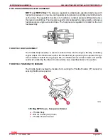
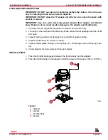
72986
IAC Valve Air Flow Diagram
Index
Содержание 305 CID (5.0L)
Страница 116: ...TROUBLESHOOTING SERVICE MANUAL NUMBER 24 Page 1C 34 90 861327 1 OCTOBER 1999 THIS PAGE IS INTENTIONALLY BLANK Index ...
Страница 142: ...MCM MODELS SERVICE MANUAL NUMBER 24 Page 2A 26 90 861327 1 OCTOBER 1999 THIS PAGE IS INTENTIONALLY BLANK Index ...
Страница 166: ...MIE MODELS SERVICE MANUAL NUMBER 24 Page 2B 24 90 861327 1 OCTOBER 1999 THIS PAGE IS INTENTIONALLY BLANK Index ...
Страница 285: ...STARTING SYSTEM SERVICE MANUAL NUMBER 24 Page 4A 30 90 861327 1 OCTOBER 1999 THIS PAGE IS INTENTIONALLY BLANK Index ...
Страница 315: ...IGNITION SYSTEM SERVICE MANUAL NUMBER 24 Page 4B 30 90 861327 1 OCTOBER 1999 THIS PAGE IS INTENTIONALLY BLANK Index ...
Страница 344: ...CHARGING SYSTEM SERVICE MANUAL NUMBER 24 90 861327 1 OCTOBER 1999 Page 4C 29 THIS PAGE IS INTENTIONALLY BLANK Index ...
Страница 345: ...CHARGING SYSTEM SERVICE MANUAL NUMBER 24 Page 4C 30 90 861327 1 OCTOBER 1999 THIS PAGE IS INTENTIONALLY BLANK Index ...
Страница 364: ...INSTRUMENTATION SERVICE MANUAL NUMBER 24 90 861327 1 OCTOBER 1999 Page 4D 19 THIS PAGE IS INTENTIONALLY BLANK Index ...
Страница 365: ...INSTRUMENTATION SERVICE MANUAL NUMBER 24 Page 4D 20 90 861327 1 OCTOBER 1999 THIS PAGE IS INTENTIONALLY BLANK Index ...
Страница 383: ...MAINTENANCE SERVICE MANUAL NUMBER Page 4E 18 90 861327 1 OCTOBER 1999 THIS PAGE IS INTENTIONALLY BLANK Index ...
Страница 721: ...DIAGNOSTICS SERVICE MANUAL NUMBER 24 Page 5G 94 90 861327 1 OCTOBER 1999 THIS PAGE IS INTENTIONALLY BLANK Index ...
Страница 779: ...GENERAL SERVICE MANUAL NUMBER 24 Page 7A 6 90 861327 1 OCTOBER 1999 THIS PAGE IS INTENTIONALLY BLANK Index ...
Страница 803: ...COLLECTORS SERVICE MANUAL NUMBER 23 Page 7C 16 90 861327 1 OCTOBER 1999 THIS PAGE IS INTENTIONALLY BLANK Index ...
Страница 859: ...HURTH TRANSMISSIONS SERVICE MANUAL NUMBER 24 Page 8C 18 90 861327 1 OCTOBER 1999 THIS PAGE IS INTENTIONALLY BLANK Index ...

