CLOSED COOLED MODELS
SERVICE MANUAL NUMBER 24
90-861327--1 OCTOBER 1999
Page 6B-7
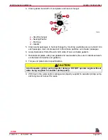
9. If no leakage could be found in above steps, engine is leaking internally. Leaking may
be caused by one or more of the following: (1) loose cylinder head bolts or damaged
gasket, (2) loose intake manifold bolts or damaged gasket, (3) loose exhaust elbow or
distribution block retaining nuts or damaged gasket, (4) cracked or porous cylinder head
or block, or (5) cracked or porous exhaust manifold. Proceed as follows until location
of internal leak is found.
a. Start engine. Re-pressurize system to previously specified amount and observe
pressure gauge on tester. If needle in gauge vibrates, compression or combustion
is leaking into closed cooling section from a leak in the combustion chamber. Exact
cylinders where leakage is taking place can sometimes be found by removing spark
plug wires (one at a time) while observing pressure gauge. Vibration will decrease
or stop when plug wire is removed from leaking cylinder. Stop engine.
b. Remove spark plugs (one at a time) from cylinders and examine for presence of
coolant. A spark plug that is perfectly clean or milky appearing is a sure indication
of a leak.
c. Drain oil from engine and examine for coolant. Oil will usually be milky if coolant is
present. If coolant is present, remove engine from boat and drop the oil pan. With
engine in the upright position, re-pressurize closed cooling section to previously
specified amount and examine internal surfaces of engine to locate leak.
d. If no leakage can be found in above steps, entire engine must be disassembled and
inspected for leakage.
Testing for Cylinder Head Gasket Leak
A leaking head gasket will cause combustion gas to be forced into the cooling system. The
mixture of coolant and tiny air bubbles is a poor heat conductor and will overheat an engine
quickly. Compression tests or cooling system pressure check normally will not detect the
leak because the test pressure is far below the combustion pressures that cause the leak.
An effective test is as follows:
IMPORTANT: Run boat in lake for this test. It is best to run the engine at or above
cruising speed during this test. Usually a failed head gasket will not cause the engine
to overheat below cruising speed.
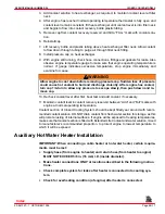
1. Install a clear plastic hose between the reservoir and coolant recovery bottle. Use a 2-3
ft. (610-910 mm) long hose for this test.
2. Route this hose so a “U” is formed.
3. Put enough coolant into hose to fill the center 4 or 5 inches (100-130 mm) of the “U.”
4. Observe the “U” while the engine is running.
a. During Idle and Warm-Up: Some coolant and/or air will leave the reservoir.
b. During Cruising Speed (2500-3500 rpm): Coolant and/or air leaving the reservoir
should stop after approximately five minutes running at a given rpm. A leaking head
gasket will produce air bubbling through the “U,” going to the coolant recovery bottle.
The frequency and size of the bubbles will depend on the size of the leak.
c. At Higher Speeds (4000+ rpm): Normal operation is the same as described in “b”
above. A failed head gasket will cause the bubbles to come faster and may be
accompanied by violent, intermittent bursts of coolant.
Index
Содержание 305 CID (5.0L)
Страница 116: ...TROUBLESHOOTING SERVICE MANUAL NUMBER 24 Page 1C 34 90 861327 1 OCTOBER 1999 THIS PAGE IS INTENTIONALLY BLANK Index ...
Страница 142: ...MCM MODELS SERVICE MANUAL NUMBER 24 Page 2A 26 90 861327 1 OCTOBER 1999 THIS PAGE IS INTENTIONALLY BLANK Index ...
Страница 166: ...MIE MODELS SERVICE MANUAL NUMBER 24 Page 2B 24 90 861327 1 OCTOBER 1999 THIS PAGE IS INTENTIONALLY BLANK Index ...
Страница 285: ...STARTING SYSTEM SERVICE MANUAL NUMBER 24 Page 4A 30 90 861327 1 OCTOBER 1999 THIS PAGE IS INTENTIONALLY BLANK Index ...
Страница 315: ...IGNITION SYSTEM SERVICE MANUAL NUMBER 24 Page 4B 30 90 861327 1 OCTOBER 1999 THIS PAGE IS INTENTIONALLY BLANK Index ...
Страница 344: ...CHARGING SYSTEM SERVICE MANUAL NUMBER 24 90 861327 1 OCTOBER 1999 Page 4C 29 THIS PAGE IS INTENTIONALLY BLANK Index ...
Страница 345: ...CHARGING SYSTEM SERVICE MANUAL NUMBER 24 Page 4C 30 90 861327 1 OCTOBER 1999 THIS PAGE IS INTENTIONALLY BLANK Index ...
Страница 364: ...INSTRUMENTATION SERVICE MANUAL NUMBER 24 90 861327 1 OCTOBER 1999 Page 4D 19 THIS PAGE IS INTENTIONALLY BLANK Index ...
Страница 365: ...INSTRUMENTATION SERVICE MANUAL NUMBER 24 Page 4D 20 90 861327 1 OCTOBER 1999 THIS PAGE IS INTENTIONALLY BLANK Index ...
Страница 383: ...MAINTENANCE SERVICE MANUAL NUMBER Page 4E 18 90 861327 1 OCTOBER 1999 THIS PAGE IS INTENTIONALLY BLANK Index ...
Страница 721: ...DIAGNOSTICS SERVICE MANUAL NUMBER 24 Page 5G 94 90 861327 1 OCTOBER 1999 THIS PAGE IS INTENTIONALLY BLANK Index ...
Страница 779: ...GENERAL SERVICE MANUAL NUMBER 24 Page 7A 6 90 861327 1 OCTOBER 1999 THIS PAGE IS INTENTIONALLY BLANK Index ...
Страница 803: ...COLLECTORS SERVICE MANUAL NUMBER 23 Page 7C 16 90 861327 1 OCTOBER 1999 THIS PAGE IS INTENTIONALLY BLANK Index ...
Страница 859: ...HURTH TRANSMISSIONS SERVICE MANUAL NUMBER 24 Page 8C 18 90 861327 1 OCTOBER 1999 THIS PAGE IS INTENTIONALLY BLANK Index ...

