VELVET DRIVE IN-LINE AND V-DRIVE TRANSMISSION
SERVICE MANUAL NUMBER 24
Page 8A-10
90-861327--1 OCTOBER 1999
Removal
NOTICE
The following procedure describes removal of transmission without removing
engine. If engine must be removed, refer to SECTION 2 (see “Table of Contents”).
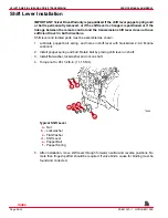
1. Drain transmission fluid.
2. Disconnect fluid cooler hoses.
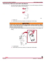
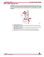
3. Disconnect shift cable.
4. Disconnect wires from neutral start safety switch.
5. Disconnect wires from fluid temperature switch.
6. Disconnect propeller shaft coupling.
7. Remove four rear mount (to engine bed) bolts.
8. Support rear part of engine with either a hoist or by using wooden blocks under flywheel
housing.
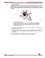
9. Remove two center transmission-to-flywheel housing attaching bolts and install two
long studs.
IMPORTANT: These two long studs will help support weight of transmission during
removal and installation.
10. Remove remaining transmission attaching bolts.
11. Pull transmission straight back and off engine.
Installation
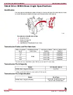
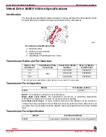
1. Check transmission output shaft rolling torque. Refer to “Specifications.”
2. Apply Quicksilver Engine Coupler Spline Grease to transmission input shaft splines and
engine drive plate splines.
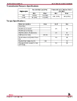
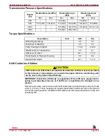
3. If removed, install rear engine mounting brackets. Torque to 45 lb-ft (61 Nm).
4. Align transmission splines with drive plate splines.
5. Slide transmission into place and secure with bolts.
6. Remove two long studs (installed in Step 9) and install remaining two bolts. Torque all
bolts to 50 lb-ft (68 Nm).
7. Relieve hoist tension and fasten rear engine mounts to engine bed. Tighten bolts
securely.
8. Connect wires to neutral start safety switch.
9. Connect wires to fluid temperature switch.
10. Connect fluid cooler hoses to transmission.
Index
Содержание 305 CID (5.0L)
Страница 116: ...TROUBLESHOOTING SERVICE MANUAL NUMBER 24 Page 1C 34 90 861327 1 OCTOBER 1999 THIS PAGE IS INTENTIONALLY BLANK Index ...
Страница 142: ...MCM MODELS SERVICE MANUAL NUMBER 24 Page 2A 26 90 861327 1 OCTOBER 1999 THIS PAGE IS INTENTIONALLY BLANK Index ...
Страница 166: ...MIE MODELS SERVICE MANUAL NUMBER 24 Page 2B 24 90 861327 1 OCTOBER 1999 THIS PAGE IS INTENTIONALLY BLANK Index ...
Страница 285: ...STARTING SYSTEM SERVICE MANUAL NUMBER 24 Page 4A 30 90 861327 1 OCTOBER 1999 THIS PAGE IS INTENTIONALLY BLANK Index ...
Страница 315: ...IGNITION SYSTEM SERVICE MANUAL NUMBER 24 Page 4B 30 90 861327 1 OCTOBER 1999 THIS PAGE IS INTENTIONALLY BLANK Index ...
Страница 344: ...CHARGING SYSTEM SERVICE MANUAL NUMBER 24 90 861327 1 OCTOBER 1999 Page 4C 29 THIS PAGE IS INTENTIONALLY BLANK Index ...
Страница 345: ...CHARGING SYSTEM SERVICE MANUAL NUMBER 24 Page 4C 30 90 861327 1 OCTOBER 1999 THIS PAGE IS INTENTIONALLY BLANK Index ...
Страница 364: ...INSTRUMENTATION SERVICE MANUAL NUMBER 24 90 861327 1 OCTOBER 1999 Page 4D 19 THIS PAGE IS INTENTIONALLY BLANK Index ...
Страница 365: ...INSTRUMENTATION SERVICE MANUAL NUMBER 24 Page 4D 20 90 861327 1 OCTOBER 1999 THIS PAGE IS INTENTIONALLY BLANK Index ...
Страница 383: ...MAINTENANCE SERVICE MANUAL NUMBER Page 4E 18 90 861327 1 OCTOBER 1999 THIS PAGE IS INTENTIONALLY BLANK Index ...
Страница 721: ...DIAGNOSTICS SERVICE MANUAL NUMBER 24 Page 5G 94 90 861327 1 OCTOBER 1999 THIS PAGE IS INTENTIONALLY BLANK Index ...
Страница 779: ...GENERAL SERVICE MANUAL NUMBER 24 Page 7A 6 90 861327 1 OCTOBER 1999 THIS PAGE IS INTENTIONALLY BLANK Index ...
Страница 803: ...COLLECTORS SERVICE MANUAL NUMBER 23 Page 7C 16 90 861327 1 OCTOBER 1999 THIS PAGE IS INTENTIONALLY BLANK Index ...
Страница 859: ...HURTH TRANSMISSIONS SERVICE MANUAL NUMBER 24 Page 8C 18 90 861327 1 OCTOBER 1999 THIS PAGE IS INTENTIONALLY BLANK Index ...

