CHARGING SYSTEM
SERVICE MANUAL NUMBER 24
Page 4C-10
90-861327--1 OCTOBER 1999
Circuitry
Perform the following tests, using a 0-20 volt DC voltmeter, to check that all of the circuits
between the alternator and the other components within the alternator system are in good
condition.
OUTPUT CIRCUIT
1. Ensure battery is fully charged by using the hydrometer test outlined in 4A.
2. Start engine and increase RPM to approximately 1500 rpm.
3. Check voltage reading. The voltage should read between 13.8 and 14.2 volts. If the
reading is below 13.8 volts:
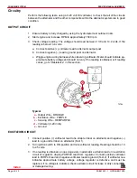
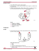
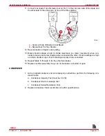
a. Connect positive (+) voltmeter lead to alternator output post.
b. Connect negative (–) lead to ground post on alternator.
c. Wiggle engine wiring harness while observing voltmeter. Meter should indicate ap-
proximate battery voltage and should not vary. If no reading is obtained, or if reading
varies, go to “Resistance” in this section.
72784
e
a
b
c
d
Typical
a -
Output Wire - ORANGE
b -
Excitation Wire - PURPLE
c -
Sensing Wire - RED/PURPLE
d -
Voltmeter (0-20 Volts)
e -
Ground
EXCITATION CIRCUIT
1. Connect positive (+) voltmeter lead to tie strap terminal on alternator and negative (–)
lead to a ground terminal on alternator (Test 1).
2. Turn ignition switch to ON position and note voltmeter reading. Reading should be 1.3
to 2.5 volts.
3. If no reading is obtained, an opening exists in alternator excitation lead or in excitation
circuit of regulator. Unplug PURPLE lead from regulator. Connect positive voltmeter
lead to PURPLE lead and negative voltmeter leads to ground (Test 2). If voltmeter now
indicates approximate battery voltage, voltage regulator is defective and must be
replaced. If no voltage is indicated, check excitation circuit for loose or dirty connections
or damaged wiring.
Index
Содержание 305 CID (5.0L)
Страница 116: ...TROUBLESHOOTING SERVICE MANUAL NUMBER 24 Page 1C 34 90 861327 1 OCTOBER 1999 THIS PAGE IS INTENTIONALLY BLANK Index ...
Страница 142: ...MCM MODELS SERVICE MANUAL NUMBER 24 Page 2A 26 90 861327 1 OCTOBER 1999 THIS PAGE IS INTENTIONALLY BLANK Index ...
Страница 166: ...MIE MODELS SERVICE MANUAL NUMBER 24 Page 2B 24 90 861327 1 OCTOBER 1999 THIS PAGE IS INTENTIONALLY BLANK Index ...
Страница 285: ...STARTING SYSTEM SERVICE MANUAL NUMBER 24 Page 4A 30 90 861327 1 OCTOBER 1999 THIS PAGE IS INTENTIONALLY BLANK Index ...
Страница 315: ...IGNITION SYSTEM SERVICE MANUAL NUMBER 24 Page 4B 30 90 861327 1 OCTOBER 1999 THIS PAGE IS INTENTIONALLY BLANK Index ...
Страница 344: ...CHARGING SYSTEM SERVICE MANUAL NUMBER 24 90 861327 1 OCTOBER 1999 Page 4C 29 THIS PAGE IS INTENTIONALLY BLANK Index ...
Страница 345: ...CHARGING SYSTEM SERVICE MANUAL NUMBER 24 Page 4C 30 90 861327 1 OCTOBER 1999 THIS PAGE IS INTENTIONALLY BLANK Index ...
Страница 364: ...INSTRUMENTATION SERVICE MANUAL NUMBER 24 90 861327 1 OCTOBER 1999 Page 4D 19 THIS PAGE IS INTENTIONALLY BLANK Index ...
Страница 365: ...INSTRUMENTATION SERVICE MANUAL NUMBER 24 Page 4D 20 90 861327 1 OCTOBER 1999 THIS PAGE IS INTENTIONALLY BLANK Index ...
Страница 383: ...MAINTENANCE SERVICE MANUAL NUMBER Page 4E 18 90 861327 1 OCTOBER 1999 THIS PAGE IS INTENTIONALLY BLANK Index ...
Страница 721: ...DIAGNOSTICS SERVICE MANUAL NUMBER 24 Page 5G 94 90 861327 1 OCTOBER 1999 THIS PAGE IS INTENTIONALLY BLANK Index ...
Страница 779: ...GENERAL SERVICE MANUAL NUMBER 24 Page 7A 6 90 861327 1 OCTOBER 1999 THIS PAGE IS INTENTIONALLY BLANK Index ...
Страница 803: ...COLLECTORS SERVICE MANUAL NUMBER 23 Page 7C 16 90 861327 1 OCTOBER 1999 THIS PAGE IS INTENTIONALLY BLANK Index ...
Страница 859: ...HURTH TRANSMISSIONS SERVICE MANUAL NUMBER 24 Page 8C 18 90 861327 1 OCTOBER 1999 THIS PAGE IS INTENTIONALLY BLANK Index ...

