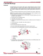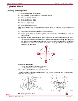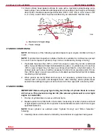
5.0l / 305 cid / 5.7l / 350 cid ENGINES
SERVICE MANUAL NUMBER 24
90-861327--1 OCTOBER 1999
Page 3A-71
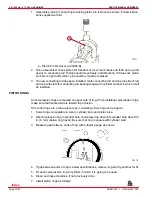
a. Install oil ring spacer in groove and insert anti- rotation tang in oil hole.
b. Hold spacer ends butted and install lower steel oil ring rail with gap properly located.
c. Install upper steel oil ring rail with gap properly located.
d. Flex the oil ring assembly to make sure ring is free. If binding occurs at any point,
the cause should be determined. If binding is caused by ring groove, remove by
dressing groove with a fine cut file. If binding is caused by a distorted ring, use a new
ring.
IMPORTANT: Use piston ring expander (91-24697) for compression ring installation.
e. Using ring expander, install lower compression ring with marked side up.
f.
Using ring expander, install top compression ring with marked side up.
Installation
IMPORTANT: Cylinder bores must be clean before piston installation. Clean with a
light honing, as necessary. Then clean with hot water and detergent wash. After
cleaning, swab bores several times with light engine oil and clean cloth, then wipe
with a clean dry cloth.
1. Lubricate connecting rod bearings.
2. Install connecting rod bearings in rods and rod caps.
3. Lightly coat pistons, rings and cylinder walls with light engine oil.
4. With bearing caps removed, install connecting rod bolt guide 3/8-24 (J-5239) on con-
necting rod bolts.
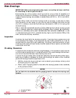
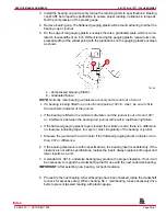
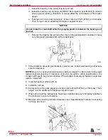
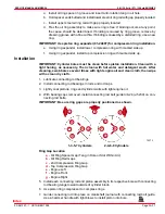
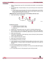
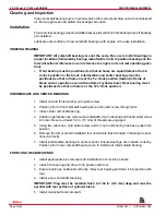
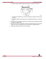
IMPORTANT: Be sure ring gaps are properly positioned as shown.
72373
e
f
g
b
b
c
a
d
b
b
c
d
a
1-3-5-7 Cylinders
2-4-6-8 Cylinders
Ring Gap Location
a -
Oil Ring Spacer Gap (Tang in Hole or Slot Within Arc)
b -
Oil Ring Rail Gaps
c -
2nd Compression Ring Gap
d -
Top Compression Ring Gap
e -
Engine Left
f -
Engine Front
g -
Engine Right
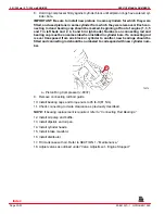
5. Install each connecting rod and piston assembly in its respective bore with connecting
rod bearing tangs toward outside of cylinder block.
6. Use piston ring compressor to compress rings.
7. Guide connecting rod into place on crankshaft journal with connecting rod bolt guide.
Use a hammer handle with light blows to install piston into bore.
Index
Содержание 305 CID (5.0L)
Страница 116: ...TROUBLESHOOTING SERVICE MANUAL NUMBER 24 Page 1C 34 90 861327 1 OCTOBER 1999 THIS PAGE IS INTENTIONALLY BLANK Index ...
Страница 142: ...MCM MODELS SERVICE MANUAL NUMBER 24 Page 2A 26 90 861327 1 OCTOBER 1999 THIS PAGE IS INTENTIONALLY BLANK Index ...
Страница 166: ...MIE MODELS SERVICE MANUAL NUMBER 24 Page 2B 24 90 861327 1 OCTOBER 1999 THIS PAGE IS INTENTIONALLY BLANK Index ...
Страница 285: ...STARTING SYSTEM SERVICE MANUAL NUMBER 24 Page 4A 30 90 861327 1 OCTOBER 1999 THIS PAGE IS INTENTIONALLY BLANK Index ...
Страница 315: ...IGNITION SYSTEM SERVICE MANUAL NUMBER 24 Page 4B 30 90 861327 1 OCTOBER 1999 THIS PAGE IS INTENTIONALLY BLANK Index ...
Страница 344: ...CHARGING SYSTEM SERVICE MANUAL NUMBER 24 90 861327 1 OCTOBER 1999 Page 4C 29 THIS PAGE IS INTENTIONALLY BLANK Index ...
Страница 345: ...CHARGING SYSTEM SERVICE MANUAL NUMBER 24 Page 4C 30 90 861327 1 OCTOBER 1999 THIS PAGE IS INTENTIONALLY BLANK Index ...
Страница 364: ...INSTRUMENTATION SERVICE MANUAL NUMBER 24 90 861327 1 OCTOBER 1999 Page 4D 19 THIS PAGE IS INTENTIONALLY BLANK Index ...
Страница 365: ...INSTRUMENTATION SERVICE MANUAL NUMBER 24 Page 4D 20 90 861327 1 OCTOBER 1999 THIS PAGE IS INTENTIONALLY BLANK Index ...
Страница 383: ...MAINTENANCE SERVICE MANUAL NUMBER Page 4E 18 90 861327 1 OCTOBER 1999 THIS PAGE IS INTENTIONALLY BLANK Index ...
Страница 721: ...DIAGNOSTICS SERVICE MANUAL NUMBER 24 Page 5G 94 90 861327 1 OCTOBER 1999 THIS PAGE IS INTENTIONALLY BLANK Index ...
Страница 779: ...GENERAL SERVICE MANUAL NUMBER 24 Page 7A 6 90 861327 1 OCTOBER 1999 THIS PAGE IS INTENTIONALLY BLANK Index ...
Страница 803: ...COLLECTORS SERVICE MANUAL NUMBER 23 Page 7C 16 90 861327 1 OCTOBER 1999 THIS PAGE IS INTENTIONALLY BLANK Index ...
Страница 859: ...HURTH TRANSMISSIONS SERVICE MANUAL NUMBER 24 Page 8C 18 90 861327 1 OCTOBER 1999 THIS PAGE IS INTENTIONALLY BLANK Index ...

