IGNITION SYSTEM
SERVICE MANUAL NUMBER 24
Page 4B-28
90-861327--1 OCTOBER 1999
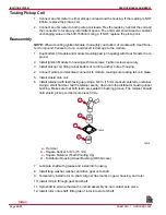
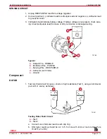
Testing Pickup Coil
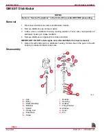
1. Connect an ohmmeter to either pickup coil lead and the housing. If the reading is NOT
infinite, replace the pickup coil.
2. Connect an ohmmeter to both pickup coil leads. Flex the leads by hand at the coil and
the connector to locate any intermittent opens. The ohmmeter should read a constant
unchanging value in the 500-1500ohm range. If NOT, replace the pickup coil.
Reassembly
NOTE: When mounting Ignition Module, thoroughly coat bottom of module with Heat Trans-
fer Compound. Failure to do so could result in damage to the module.
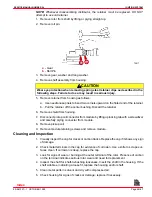
1. Coat bottom of module and module mounting pad (on housing) with Heat Transfer Com-
pound.
2. Install Ignition Module to housing with two screws. Tighten screws securely.
3. Install pickup coil, fitting tab at bottom of coil into anchor hole of housing.
4. Connect pickup coil electrical connector to module, making sure locking tab is in place.
5. Install shield onto coil.
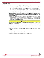
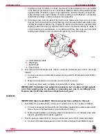
6. Install retainer (with teeth facing up) using a 5/8 in. (15 mm) socket centered on retainer.
Using a small hammer, tap the retainer evenly, down onto the distributor housing upper
bushing. Make sure that both teeth are seated in bushing groove. The retainer should
hold shield, pickup coil and pole piece firmly.
72919
c
d
b
a
76522
a -
Hammer
b -
Square Socket, 5/8 in (15 mm)
c -
Square Retainer (Teeth Pointing Up)
d -
Distributor Housing Upper Bushing (With Groove)
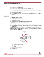
7. Lubricate shaft with grease and install into housing.
8. Install tang washer, washer and drive gear onto shaft.
9. Temporarily install rotor on shaft. Align scribe marks on gear, housing, and rotor.
10. Install roll pin through gear and shaft.
11. Spin shaft to ensure that teeth on shaft assembly do not contact pole piece.
12. Install rotor onto shaft, fitting tab of rotor into slot of shaft.
Index
Содержание 305 CID (5.0L)
Страница 116: ...TROUBLESHOOTING SERVICE MANUAL NUMBER 24 Page 1C 34 90 861327 1 OCTOBER 1999 THIS PAGE IS INTENTIONALLY BLANK Index ...
Страница 142: ...MCM MODELS SERVICE MANUAL NUMBER 24 Page 2A 26 90 861327 1 OCTOBER 1999 THIS PAGE IS INTENTIONALLY BLANK Index ...
Страница 166: ...MIE MODELS SERVICE MANUAL NUMBER 24 Page 2B 24 90 861327 1 OCTOBER 1999 THIS PAGE IS INTENTIONALLY BLANK Index ...
Страница 285: ...STARTING SYSTEM SERVICE MANUAL NUMBER 24 Page 4A 30 90 861327 1 OCTOBER 1999 THIS PAGE IS INTENTIONALLY BLANK Index ...
Страница 315: ...IGNITION SYSTEM SERVICE MANUAL NUMBER 24 Page 4B 30 90 861327 1 OCTOBER 1999 THIS PAGE IS INTENTIONALLY BLANK Index ...
Страница 344: ...CHARGING SYSTEM SERVICE MANUAL NUMBER 24 90 861327 1 OCTOBER 1999 Page 4C 29 THIS PAGE IS INTENTIONALLY BLANK Index ...
Страница 345: ...CHARGING SYSTEM SERVICE MANUAL NUMBER 24 Page 4C 30 90 861327 1 OCTOBER 1999 THIS PAGE IS INTENTIONALLY BLANK Index ...
Страница 364: ...INSTRUMENTATION SERVICE MANUAL NUMBER 24 90 861327 1 OCTOBER 1999 Page 4D 19 THIS PAGE IS INTENTIONALLY BLANK Index ...
Страница 365: ...INSTRUMENTATION SERVICE MANUAL NUMBER 24 Page 4D 20 90 861327 1 OCTOBER 1999 THIS PAGE IS INTENTIONALLY BLANK Index ...
Страница 383: ...MAINTENANCE SERVICE MANUAL NUMBER Page 4E 18 90 861327 1 OCTOBER 1999 THIS PAGE IS INTENTIONALLY BLANK Index ...
Страница 721: ...DIAGNOSTICS SERVICE MANUAL NUMBER 24 Page 5G 94 90 861327 1 OCTOBER 1999 THIS PAGE IS INTENTIONALLY BLANK Index ...
Страница 779: ...GENERAL SERVICE MANUAL NUMBER 24 Page 7A 6 90 861327 1 OCTOBER 1999 THIS PAGE IS INTENTIONALLY BLANK Index ...
Страница 803: ...COLLECTORS SERVICE MANUAL NUMBER 23 Page 7C 16 90 861327 1 OCTOBER 1999 THIS PAGE IS INTENTIONALLY BLANK Index ...
Страница 859: ...HURTH TRANSMISSIONS SERVICE MANUAL NUMBER 24 Page 8C 18 90 861327 1 OCTOBER 1999 THIS PAGE IS INTENTIONALLY BLANK Index ...

