FUEL INJECTION DESCRIPTIONS AND SYSTEM OPERATION
SERVICE MANUAL NUMBER 24
Page 5D-20
90-861327 OCTOBER 1999
DISCRETE SWITCH INPUTS
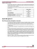
Several discrete switch inputs are utilized by the system to identify abnormal conditions that
may affect engine operation. These switches are used in conjunction with the ECM to detect
critical conditions to engine operation.
The switches which are used with the fuel injection system to detect critical engine operation
parameters are:
Switch
Normal State
Oil Pressure
N/O
(With Pressure)
Gear Lube Monitor
Level on Sterndrive
N/O
(When Full)
Transmission Temperature on MCM Models with
Two-Speed Transmission
N/O
(When Cold)
Transmission Temperature on MIE Models
N/O
(When Cold)
Spark Management
High Energy Ignition with Ignition Control (IC)
The Electronic Fuel Injection is controlled by an Engine Control Module (ECM). This module
is the nerve/decision center of the system. It uses all the information it gathers to manage
ignition spark, delivering increased fuel economy and maximum engine performance.
The system uses inputs from sensors to make decisions on the amount of spark advance
or retard allowed.
The system has been designed to control ignition advance and retard electronically by the
ECM.
In order for the ECM to properly calculate spark advance, it must always know at what speed
the engine is running. The engine speed signal is accomplished by a circuit within the distrib-
utor module which converts the pickup coil voltage to a square wave reference signal that
can be used by the ECM. This square wave engine speed reference signal is known as REF
HI. With MEFI 1 or MEFI 2, the ECM must also have something to compare the REF HI value
against. Therefore, an additional line is provided between the ECM and the distributor mod-
ule that is known as REF LO. These two lines, between the ECM and the distributor, provide
a precise indication of engine speed.
With MEFI 1 or MEFI 2, the two other lines between the ECM and distributor that control the
Ignition Control (IC) operation are known as the bypass and IC circuits.
Index
Содержание 305 CID (5.0L)
Страница 116: ...TROUBLESHOOTING SERVICE MANUAL NUMBER 24 Page 1C 34 90 861327 1 OCTOBER 1999 THIS PAGE IS INTENTIONALLY BLANK Index ...
Страница 142: ...MCM MODELS SERVICE MANUAL NUMBER 24 Page 2A 26 90 861327 1 OCTOBER 1999 THIS PAGE IS INTENTIONALLY BLANK Index ...
Страница 166: ...MIE MODELS SERVICE MANUAL NUMBER 24 Page 2B 24 90 861327 1 OCTOBER 1999 THIS PAGE IS INTENTIONALLY BLANK Index ...
Страница 285: ...STARTING SYSTEM SERVICE MANUAL NUMBER 24 Page 4A 30 90 861327 1 OCTOBER 1999 THIS PAGE IS INTENTIONALLY BLANK Index ...
Страница 315: ...IGNITION SYSTEM SERVICE MANUAL NUMBER 24 Page 4B 30 90 861327 1 OCTOBER 1999 THIS PAGE IS INTENTIONALLY BLANK Index ...
Страница 344: ...CHARGING SYSTEM SERVICE MANUAL NUMBER 24 90 861327 1 OCTOBER 1999 Page 4C 29 THIS PAGE IS INTENTIONALLY BLANK Index ...
Страница 345: ...CHARGING SYSTEM SERVICE MANUAL NUMBER 24 Page 4C 30 90 861327 1 OCTOBER 1999 THIS PAGE IS INTENTIONALLY BLANK Index ...
Страница 364: ...INSTRUMENTATION SERVICE MANUAL NUMBER 24 90 861327 1 OCTOBER 1999 Page 4D 19 THIS PAGE IS INTENTIONALLY BLANK Index ...
Страница 365: ...INSTRUMENTATION SERVICE MANUAL NUMBER 24 Page 4D 20 90 861327 1 OCTOBER 1999 THIS PAGE IS INTENTIONALLY BLANK Index ...
Страница 383: ...MAINTENANCE SERVICE MANUAL NUMBER Page 4E 18 90 861327 1 OCTOBER 1999 THIS PAGE IS INTENTIONALLY BLANK Index ...
Страница 721: ...DIAGNOSTICS SERVICE MANUAL NUMBER 24 Page 5G 94 90 861327 1 OCTOBER 1999 THIS PAGE IS INTENTIONALLY BLANK Index ...
Страница 779: ...GENERAL SERVICE MANUAL NUMBER 24 Page 7A 6 90 861327 1 OCTOBER 1999 THIS PAGE IS INTENTIONALLY BLANK Index ...
Страница 803: ...COLLECTORS SERVICE MANUAL NUMBER 23 Page 7C 16 90 861327 1 OCTOBER 1999 THIS PAGE IS INTENTIONALLY BLANK Index ...
Страница 859: ...HURTH TRANSMISSIONS SERVICE MANUAL NUMBER 24 Page 8C 18 90 861327 1 OCTOBER 1999 THIS PAGE IS INTENTIONALLY BLANK Index ...

