Meler MACRO FOAM Series Скачать руководство пользователя страница 38

FOCKE MELER GLUING SOLUTIONS, S.A.

4-4

MELTER OPERATION

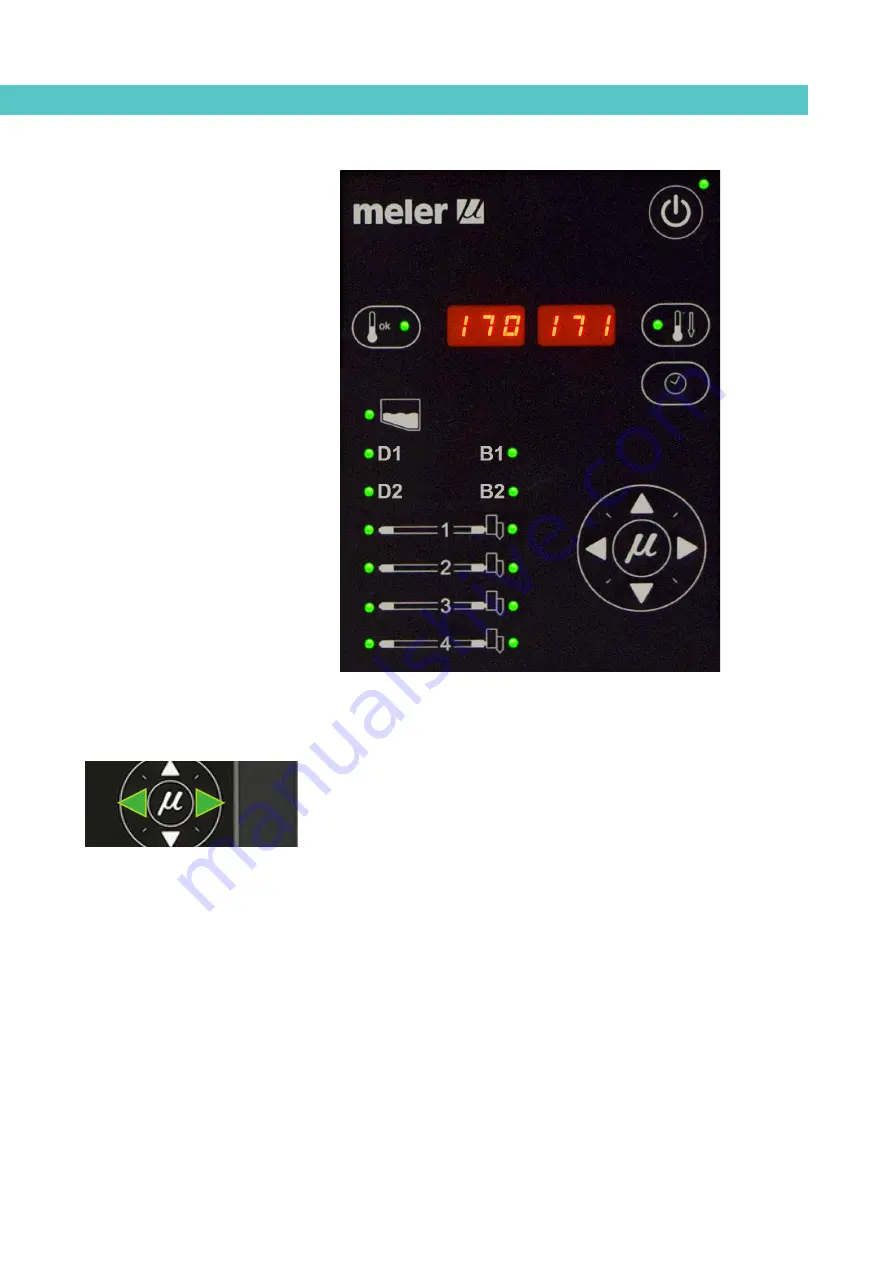
Displaying the temperature for each component

The temperature may be displayed for each component (premelter, tank, 

distributor and each hose and applicator) by selecting the component with the 

cursor.

Press the left-right arrow until the desired component is displayed.

After 10 seconds, the display will return to the default component (the tank).

If you wish to keep the component displayed permanently, press and hold the 

left-right arrow for 2 seconds while selecting the chosen element.

For units that have one pump installed, the display sequence is the following: 

premelter<—tank<—distributor 1<—pump 1<—distributor 2<—pump 2<— 

hose 1<—applicator 1<—...<—hose 4<—applicator 4

premelter—>tank—>distributor 1—>pump 1—>distributor 2—>pump 2—> 

hose 1—>applicator 1—>...—>hose 4—>applicator 4 

To remove a component from permanent display, simply press either of the 

left-right arrows.

Содержание MACRO FOAM Series

Страница 1: ...MA 5127 ENG 231220 GLUING SOLUTIONS ADHESIVE MELTER MACRO FOAM SERIES INSTRUCTIONS MANUAL ...

Страница 2: ... without the express authorization of its owner is strictly prohibited The specifications and information contained in this manual may be modified without prior notice The official language of this manual is only the English language The remaining versions of the manual in other languages are mere translations without any official value or efficacy In case of discrepancies or contradictions betwee...

Страница 3: ...nents 1 2 Pneumatic components 1 2 Thermal components 1 3 Materials 1 3 Noise emission declaration 1 3 Intended use 1 4 Limited use 1 4 2 INTRODUCTION 2 1 Description 2 2 Intended use 2 2 Limited use 2 2 Modes of operation 2 2 Hot melt melter identification 2 3 Main components 2 4 Control card components 2 6 Pumping control card components 2 7 Optional Equipment 2 8 Three color ligh beacon 2 8 ...

Страница 4: ...4 Pneumatic connection 3 5 Hose and applicator connection 3 5 Parameter Programming 3 6 Programming working temperatures 3 6 Selecting the overheating value 3 6 Keeping a component on display 3 7 External I O connections 3 8 Temperature ok 3 8 External Standby 3 9 Low level optional 3 9 Output inhibitor 3 10 Starting up the motor ok ext 3 11 Foam pump pressure regulation ref ext 3 11 Failures outp...

Страница 5: ...isabling the equipment activation deactivation program 4 10 Programming the equipment s standby function activation deactivation 4 11 Disabling the equipment standby function programming 4 12 Special function buttons 4 13 Pumping control 4 14 Starting up the pump control card 4 14 Pumping safety measures 4 14 Password security 4 15 LED indicators 4 16 Modes of operation 4 17 Mode of operation with...

Страница 6: ...g light 4 27 Level sensor adjustments 4 28 Sensitivity adjustment 4 28 Level stabilisation time 4 28 Programmable times using the timer 4 28 Disconnection delay time 4 28 Operating alarms 4 28 Setting programmable times using the timer 4 29 Manual feeding 4 30 Turning off the melter equipment 4 30 Conditions for good performance 4 30 5 MAINTENANCE 5 1 Equipment cleaning 5 1 Depressurizing the syst...

Страница 7: ...ricants 5 7 Thermostats maintenance 5 8 6 TECHNICAL CHARACTERISTICS 6 1 General 6 1 Dimensions 6 2 7 ELECTRICAL DRAWINGS 7 1 8 PNEUMATIC DIAGRAMS 8 1 Components list 8 1 Pneumatic by pass valve control system 8 1 9 SPARE PARTS LIST 9 1 A COVER TANK ASSEMBLY MACRO FOAM 35 9 2 B COVER TANK ASSEMBLY 9 3 C DISTRIBUTOR ASSEMBLY 9 4 D FILTER PURGE AND PRESSURE VALVE ASSEMBLY 9 5 E GEARED MOTOR PUMP ASSE...

Страница 8: ...FOCKE MELER GLUING SOLUTIONS TABLE OF CONTENTS This page is intentionally left blank ...

Страница 9: ... perform maintenance on it Also provide necessary safety material appropriate clothing footwear gloves and safety glasses In all cases observe local regulations regarding risk prevention and safety Symbols The symbols used on both the melter applicator equipment and in this manual always represent the type of risk we are exposed to Failure to abide by a warning signal may result in personal injury...

Страница 10: ...voltage Periodically inspect the cables to check for crushing wear and tear as well as to prevent tripping and falls as a result of their placement Although the system meets EMC requirements it is inadvisable to use devices that transmit high levels of radiation i e mobile phones or soldering equipment in their vecinity Hydraulic components As this is a pressurized system precautions related to th...

Страница 11: ...Meler systems are designed for use with hot melt adhesives They should not be used with any other type of material and especially not with solvents which may cause personal injury or damage to internal system components Some units are specifically designed to use polyurethane reactive PUR hot melt adhesives Using PUR on a unit that is not prepared for that purpose may cause severe damage to the un...

Страница 12: ...bels accompanying the equipment using adequate means of protection during each mode of operation Limited use The equipment should never be used under the following conditions Use with reactive polyurethane or any other material that might cause safety or health risks when heated Use of equipment in environments where cleaning is necessary using water jets Use of equipment to heat or melt food prod...

Страница 13: ...eries The Macro series includes the 35 50 and 120 liter range of hot melt adhesive melters Most of the photographs and illustrations that appear in this manual refer to the 35 liter Macro Foam melter This model has been used as a reference for writing this manual as its main characteristics with the exception of the tank capacity and the connection outputs are the same as those in the rest of the ...

Страница 14: ...he safety instructions indicated in this manual as well as on the labels accompanying the equipment using adequate means of protection during each mode of operation Limited use The Macro Foam series hot melt melters must be used for their intended uses and never in the following conditions Use with adhesives or any other material that might cause safety or health risks when heated Use of hot melt ...

Страница 15: ...led by means of an external 0 10 V signal sent from the main machine Standby mode_The hot melt melter remains in a resting state with the materials kept at programmable temperature values below the pre selected value The pump remains deactivated Alarm mode_The hot melt melter detects a malfunction and warns the operator of this event The pump remains deactivated Stop mode_The hot melt melter remai...

Страница 16: ...FOCKE MELER GLUING SOLUTIONS S A 2 4 INTRODUCTION Main components 9 1 2 3 4 5 6 8 10 11 12 15 16 18 19 20 18 19 20 7 18 17 14 13 21 ...

Страница 17: ...ional 10 Tank access cover 11 Gas pressure regulator to pump 1 12 Gas pressure regulator to pump 2 13 Unit transport wheels 14 External adhesive feeding inlet optional 15 Pneumatic by pass valve pressure control with pressure gauge pump 1 16 Pneumatic by pass valve pressure control with pressure gauge pump 2 17 Hose applicator electrical connections Right side or rear placed 18 Hose output distrib...

Страница 18: ...icator LED 3 Distribuitors indicators LEDS 4 Temperature set point 5 Real temperature 6 ON OFF switch 7 Standby function 8 Time scheduling 9 Pumps indicators LEDS 10 Left right button channel selection 11 Up down button temperature modification 12 Applicator indicator LED 13 Hose indicator LED 1 2 3 6 7 8 9 10 4 5 11 12 13 ...

Страница 19: ...4 Pumping permission LED 5 Up down arrow keys for selecting values 6 Left right arrow keys for selecting options 7 Speed ramp steps display screen 8 Speed ramp value selection LEDs voltage speed 9 Voltage pump speed errors display screen 10 Pumping control internal external selection 11 Pumping speed internal external selection 12 Voltage value display of the external signal of the speed control ...

Страница 20: ...to provide the melting equipment with more functions the following optional elements may be added Low melted adhesive level detection system Light tower system Automatic tank filling system Three color ligh beacon RED Gas bottle empty WHITE Low adhesive level GREEN Temperature OK ...

Страница 21: ...ording to the location and connections in each particular installation Anchoring screws for the melter equipment if required Power cord and plug for electrical power Pneumatic conduct and connection to the compressed air system Multicore cable for external electrical control Optionally a gas ventilation system Installation requirements Before installing Macro Foam series melter equipment we must m...

Страница 22: ...uits by circuit breaker and install appropriate personal protection leads to mass by differential switch Consumption figures according to melter and output configuration are included in the table in the section Electrical power connection Compressed air As an option a pneumatically activated by pass valve may be installed If this is added to the system a dry unlubricated compressed air network mus...

Страница 23: ...elter it should be removed from its location on a pallet and examined in order to detect any possible breakage or deterioration Communicate any defect even to the outer packing materials to your Meler Representative or to the Main Office Contents The Macro Foam series packing materials may contain accessories that form part of the same order If this is not the case the following are the standard c...

Страница 24: ...ng Pg 21 in the area reserved for them fastening them to the plate with the appropriate nut Open the electric cabinet door as far as possible Thread the power cord Ø14 18 mm through the electrical wall bushing Pg 21 and fasten it to the inside anchor making sure that the cord reaches the power terminals block inside the cabinet Connect each wire in the power cord to its corresponding place on the ...

Страница 25: ...may be connected to this equipment Up to four hose applicator outputs may be connected to 50 and 120L Macro Foam melters depending on the number of pumps installed Warning When connecting hose applicator outputs verify that the connected power is not above the maximum allowable power for each output The Macro Foam series melting equipment is equipped with a hydraulic distributor for each pump with...

Страница 26: ...nal purposes Programming working temperatures The melters leave the factory with the following set point temperatures 160 C 320 F for the tank premelter and the distributor 150 C 302 F for hoses 160 C 320 F for applicators The general process for modifying set up temperature values for any component is described below 1 Select the component for which you wish to modify the value with the left righ...

Страница 27: ...the tank temperatures will once again be displayed All the special menu values will be saved Keeping a component on display By default the main display shows the tank temperatures However it is possible to display indefinitely the temperatures of any component for analysis or tracking 1 Select the component you wish to see permanently with the left right arrow The corresponding LED will blink rapi...

Страница 28: ...licator output via a non voltage contact With a closed contact the output remains activated output on with an open contact it is deactivated output off Motor start up_for each pump installed the motor start up may be controlled by closing an external non voltage contact Foam pump pressure regulation_for each pump installed the foam pump pressure may be controlled by means of a 0 to 10V DC external...

Страница 29: ...sible Thread the power cord Ø4 8 mm through the wall bushing Pg13 and fasten it to the inside anchor making sure that the cord reaches the power card connector at the position where it will be installed 3 Remove the connector from the card and connect the two cable wires to their corresponding connector terminals contact NO contact NO 4 Reconnect the card connector 5 Make sure that the cable is we...

Страница 30: ... be installed 3 Remove the connector from the card and connect the two cable wires to their corresponding connector terminals 1 common voltage output 2 input for inhibitor output 1 3 input for inhibitor output 2 4 input for inhibitor output 3 5 input for inhibitor output 4 6 input for inhibitor output 5 7 input for inhibitor output 6 8 without connection 4 Reconnect the card connector 5 Make sure ...

Страница 31: ...mm2 two wire cable 2 Thread the power cord max Ø12 5 mm through the electrical wall bushing Pg13 and fasten it to the inside anchor making sure that the cord reaches the power card connector 3 Connect the two wires from the foam pump pressure regulation signal to the terminals XV11 and XV12 pump 1 or XV21 and XV22 pump 2 This is a double terminal which makes it necessary to connect each wire in on...

Страница 32: ... 1 If this is the only signal being connected use 0 5 mm2 two wire cable 2 Thread the power cord max Ø12 5 mm through the electrical wall bushing Pg13 and fasten it to the inside anchor making sure that the cord reaches the power card connector 3 Connect the two wires from the gas low level signal to the terminals 8X81 and 8X82 This is a double terminal which makes it necessary to connect each wir...

Страница 33: ... adhesive feeder order signal to the terminals 17X11 and 17X12 This is a double terminal which makes it necessary to connect each wire in one of the two holes in the terminal Since this contact is not under voltage there is no connection polarity 4 Make sure that the cables are firmly attached by the terminal screws Warning It must be connected to 24 AC or DC voltage with a maximum current of 1A P...

Страница 34: ...FOCKE MELER GLUING SOLUTIONS S A 3 14 INSTALLATION This page is intentionally left blank ...

Страница 35: ...ps It has its own control and is identified on the front panel by the corresponding picture Distributors are connected to channels number 1 to 4 with independent set point values and temperature controls The second group is the hose group These are identified on the front panel from No 1 to No 4 and by a picture of the corresponding hose Each has its own set point value The third group is the appl...

Страница 36: ...e melter s switch If the control card was turned off the last time the machine was disconnected it will remain turned off when the machine is started up again time display If the control card was on the last time that the machine was disconnected it will turn on when the machine is started up again 2 Press the ON OFF button on the control card to turn it on if it is not already activated By defaul...

Страница 37: ...ms They are equipped with LED indicators to display the heating of each component as well as the pump activations and the main machine connection signal They are also equipped with LEDs indicating equipment connection disconnection and standby function connection disconnection LED display Component heating Component status constantly lit constant low temperature blinking slowly as need according t...

Страница 38: ... will return to the default component the tank If you wish to keep the component displayed permanently press and hold the left right arrow for 2 seconds while selecting the chosen element For units that have one pump installed the display sequence is the following premelter tank distributor 1 pump 1 distributor 2 pump 2 hose 1 applicator 1 hose 4 applicator 4 premelter tank distributor 1 pump 1 di...

Страница 39: ...ributor4 off off off Err 5 hose 1 broken sensor only hose1 off off off Err 6 applicator 1 broken sensor only applicator1 off off off Err 7 hose 2 broken sensor only hose2 off off off Err 8 applicator 2 broken sensor only applicator2 off off off Err 9 hose 3 broken sensor only hose3 off off off Err 10 applicator 3 broken sensor only applicator3 off off off Err 11 hose 4 broken sensor only hose4 off...

Страница 40: ...ted by using the up down arrow keys pumping pressure internal reference through a voltage signal from the main machine or by modifying the full scale pumping pressure external reference The pump pressure work must be adjusted to the requirements of the application Warning Although pressure can be selected between 0 and 85 bar it is not advisable to operate at pressures of less than 10 bar the flow...

Страница 41: ...d be repeated for each of the components whose set point temperature value you wish to modify Programming the applicator parameters 1 Simultaneously press the buttons with the clock symbol and the down arrow to enter the special menu The choice of temperature display units C or F will appear on the display 2 Select the desired value using the up down arrow 3 Use the right arrow to move to the next...

Страница 42: ...ot melt is low the alarm n will be displayed on the screen and the external signal contact will be activated 11 Use the right arrow to return to the initial parameter 12 For any parameter the left arrow may be used to exit the special menu and display the tank temperatures once again To record any parameter you must always move to the next parameter using the right arrow Setting the clock Macro Fo...

Страница 43: ... the right arrow button will exit this program and return to the tank temperature display Programming equipment activation deactivation You may program an activation and a deactivation time for every day of the week from Monday 1 to Sunday 7 Time is expressed in 15 minute increments so we cycle from 10 0 10 hours and 0 minutes to 10 1 10 hours and 15 minutes to 10 2 10 hours and 30 minutes to 10 3...

Страница 44: ...n time programmed for the current day Disabling the equipment activation deactivation program It is possible to disable the equipment activation deactivation programming without canceling the daily programming This way the programmed data is saved but the programming will have no effect on the equipment 1 Press the button with the clock symbol A 0 will appear on the display indicating the program ...

Страница 45: ... will appear indicating the first day in the standby function programming Since the current time and date are values common to both programs the value 0 does not appear in this menu 3 Use the up down arrow to select the desired value for the day of the week Monday 1 to Sunday 7 4 Press the button with the clock symbol once again Two times will appear one in each display The left display shows the ...

Страница 46: ...ut canceling the daily programming This way the programmed data is saved but the programming will have no effect on the equipment 1 Press the button with the clock symbol A 0 will appear on the display indicating the program for current day and hour information 2 Press the standby function button A 1 will appear indicating the first day in the standby function programming 3 Use the up down arrow t...

Страница 47: ...0 of 160 C The three means for activating the standby function available with Macro Foam melters have the following priority protocols 1 Manual standby function button 2 Standby function external signal 3 Standby function activation deactivation programming Therefore if the function is activated by any of the three means it may always be deactivated using the manual button On the other hand if it ...

Страница 48: ...g up unexpectedly the control panel features by default a safety option that prevents pumping from commencing until enabled by pressing the ON OFF button on the control card This function may be disabled in the User configuration menu For the pumping control to allow the pump to operate the pumping ON OFF button must be pressed leaving it enabled the red LED on the pumping ON OFF button will turn ...

Страница 49: ...ption selected in the password security configuration is 1 security enabled only the control card ON OFF and pumping ON OFF buttons will be operational While this security option is programmed in order to avoid the need to turn off and restart the machine to return to the User configuration menu on pressing any key except the control card ON OFF and pumping ON OFF buttons a password will be requir...

Страница 50: ...s are green in colour 4 Int and ext ref LEDs when the equipment is operating in internal reference mode the int LED will be illuminated and the ext LED turned off When the equipment is operating in external reference mode the ext LED will be illuminated and the int LED will be turned off These can never be both on or both off at the same time These LEDs are green in colour 5 Ext on LED when the eq...

Страница 51: ...the equipment temperature is OK That pumping is enabled with the pumping ON OFF button red LED is turned off That the failure input is not activated E5 in which case starting the pump would be impossible In case of the pump be operating and this input is activated pumping will cease immediately If a pressure has been previously set this value will be shown on the display and the pump will start to...

Страница 52: ...e main machine reaches input E2 and its value is not 0 That the input for pumping permission E4 at central control is activated as pumping is not possible unless the equipment temperature is OK That pumping is enabled with the pumping ON OFF button red LED is turned off That the failure input is not activated E5 in which case starting the pump would be impossible In case of the pump be operating a...

Страница 53: ...rol In this operating mode pumping is controlled from the main machine while pressure is controlled from the equipment Follow the pressure below to use this operating mode 1 Press the ON OFF button to light up the control card 2 Select ok in the position ext and ref in the position int The on ext LED will be illuminated when temperature is ok To activate the start up status all of the following co...

Страница 54: ...rd is disabled with its ON OFF button The pumping ON OFF button is pressed red LED is illuminated When the pumping permission input is deactivated E3 When a variator error signal is activated E5 When the MAXIMUM PRESSURE ALARM TIME appears When the MINIMUM PRESSURE ALARM TIME appears The maximum full scale for admissible pressure is 85 bar This full scale can be adjusted by reducing this value in ...

Страница 55: ... signal has been received if a work pressure has been previously set this value will appear on the display and the pump will start to work at the indicated pressure If not the pressure must be adjusted to the value required for the application There are three ways to do this 1 Change the voltage applied from the main machine 2 Change the full scale see section 1 MAXIMUM PRESSURE ALARM User configu...

Страница 56: ...ablished in this field MAXIMUM PRESSURE error will be activated the pump will stop and an error message will be displayed By default this value is 30 seconds 3 MINIMUM PRESSURE ALARM this will be a value set between 0 and the value programmed in the MAXIMUM PRESSURE field This value may never be greater than the value programmed in the MAXIMUM PRESSURE ALARM field If the value programmed is 0 the ...

Страница 57: ...E L error is shown on the control card To reset this error you must turn off and start up the control card with its ON OFF button Variator alarm This alarm is triggered when the control card input is activated by a variator error signal When this alarm is triggered an E U error is shown on the control card The error message will be maintained while the variator error input E5 remains active As soo...

Страница 58: ...table If at any point the maximum value for Vin 10 V is entered the corresponding values for Vin and PRESSURE at higher points will be automatically updated according to the value for this point If at any point the maximum value is entered that is PRESSURE bar MAXIMUM PRESSURE the corresponding values for PRESSURE at higher points will be automatically updated to MAXIMUM PRESSURE V Vi in n P Pr re...

Страница 59: ...y to go to the next point The IN LED to the position OFF and the OUT LED to the position ON 3 XXX which means that the output pressure value is being programmed for point 3 with the up down arrow keys the value may be modified within a range from 000 to MAXIMUM PRESSURE press the right arrow key to go to the next point The IN LED to the position ON and the OUT LED to the position OFF 4 XXX which m...

Страница 60: ...w these steps 1 Unlock the pressure regulator control by pulling on it gently 2 Turn it clockwise to increase the pressure This will be seen reflected on the pressure gauge located next to it Start up and operation of the loader The automatic pellet feeder operates fully automatically regardless of whether the equipment temperature is OK for example if the equipment is running it will begin to loa...

Страница 61: ...th the open lid alarm activated when loading is activated and if the lid is still open it will wait the programmed time to activate the open lid alarm Colourless warning light If the equipment has the warning light optional feature the colourless warning light statuses are as follows 1 OFF the equipment s level is high enough 2 Steady on the equipment is loading EV ON 3 Very slow flashing load blo...

Страница 62: ...by editing the program The default time is 2 seconds Programmable times using the timer Disconnection delay time The extra time that the loader operates after the correct level has been reached is called the disconnection delay time The screen shows T EV 00 00s and you can program the first digits in seconds and the digits after the in hundredths of a second Operating alarms 1 Load error alarm Eac...

Страница 63: ...the loading cycle stops if it had not yet begun or does not begin if the equipment is in standby The electrovalve output is deactivated the warning light flashes quickly and the buzzer starts The screen shows T AL 00 00m and you can program the first digits in minutes and the digits after the in seconds Setting programmable times using the timer Inside the electric cabinet there is a programmable ...

Страница 64: ...ment If you need to disconnect the melter equipment 1 Turn off each pump control card installed in the unit 2 Turn off the machine switch on the door of the electrical cabinet 3 Reduce the pressure to 0 using by pass valve in the case of pneumatic control 4 Disconnect the pneumatic power to the applicators and the electrical power to the control unit programmer if there is one Conditions for good ...

Страница 65: ...lt in injury or death Clean the exterior using a cloth moistened with water Do not use flammable liquids or solvents To carry out external cleaning Use cleaning products compatible with polyamide materials Apply the cleaning product with a soft cloth Do not use sharp tools or scrapers with sharp edges Operation Frecuency Refer to External cleaning Daily Equipment cleaning System depressurization B...

Страница 66: ...ind when performing any operation on the hydraulic circuit Before disconnecting any hydraulic element or opening any distributor outlet it is necessary to perform the following steps 1 Disconnect the equipment switch located on the front 2 Operate the purge valve housed in each distributor to free any residual pressure from the circuit 3 Manually purge or use the corresponding control command all ...

Страница 67: ...urge valve 3 Using a 15 mm wrench unscrew the hexagonal filter cap and remove it 4 Unscrew the filter cartridge in a clockwise direction 5 Depending on the dirt inside the cartridge clean it or dispose of it directly abiding by any existing waste regulations 6 Screw back the cartridge back onto the filter cap in a counterclockwise direction 7 Replace the filter seal if damaged 8 Place the assembly...

Страница 68: ...vered on the inside with PTFE and inclined enough to aid unloading the hot melt and to avoid it from being retained inside when consequential burning occurs Furthermore when adhesives are mixed reactions may occur between them causing a degeneration and thus problems in unloading in the direction of the pump Therefore it is recommended to clean the deposit every time that A change is made to a dif...

Страница 69: ...er and attach it to the corresponding cartridge Reinstall it in the distributor 8 Refill the tank with adhesive wait for it to melt and continue working as usual Warning Whenever you handle the filter or any other element subject to pressure you must always perform a system depressurization first see the corresponding section Emptying the tank During normal maintenance activities it is recommended...

Страница 70: ... leaking through it On occasion some adhesive may leak out which makes it necessary to retighten the screws or change the gasket Warning Changing the gasket with a hot pump Release the shaft coupling from the pump Retighten or remove the screws that hold the gasket in place Replace the gaskets and reassemble the parts Occasionally as a result of the system s heating cooling cycles it may be necess...

Страница 71: ...ective cover if necessary Checking the lubricant The gear reducers are delivered filled with synthetic grease for lubrication free of outside contamination for life Ambient temperature 0 40 C with peaks of as low as 20 C and up to 50 C Use only those lubricants recommended by the manufacturer The use of other types may cause premature wear or damage to the gear reducer If the unit features a 0 375...

Страница 72: ...eactivated follow these instructions to reset them 1 Remove the side plate as shown in the image 2 Lift the insulating blanket and locate the thermostats 3 After the blanket has been lifted off the thermostats identify the thermostat that has been deactivated and press its corresponding button to reset it see Figure ...

Страница 73: ... 4 260 W per phase 2 outputs 5 560 W per phase 4 outputs 6 720 W per phase 4 outputs Temperatures ok output Low level signal Standby input External outlet inhibitor Motor start up input Foam Pump pressure control input Failures in pumping card output Low gas alarm output External loader adhesive output 3N 400V 50 60 Hz PE 0 to 40 C 1150x510x1825 120 liters 1 6 3 3 6 6 cc rev 120 kg h Up to 4 singl...

Страница 74: ...FOCKE MELER GLUING SOLUTIONS S A 6 2 TECHNICAL CHARACTERISTICS Dimensions Macro 120 Macro 50 1825 510 1150 1120 1120 1825 875 1150 ...

Страница 75: ...ELECTRICAL DRAWINGS 7 1 MA 5127 ENG MACRO FOAM SERIES MELTER MANUAL 7 ELECTRICAL DRAWINGS ...

Страница 76: ...FOCKE MELER GLUING SOLUTIONS S A 7 2 ELECTRICAL DRAWINGS This page is intentionally left blank ...

Страница 77: ...ist Pneumatic by pass valve control system 1 Pressure regulator 1 10 bar 2 Pressure gauge 0 10 bar 3 Pneumatic limit control valve ENTRADA AIRE AIR INPUT VÁLVULA LIMITADORA PRESSURE LIMIT VALVE RELACIÓN RATIO 1 15 3 1 2 MANÓMETRO MANOMETER P 0 10 bar REGULADOR DE PRESIÓN PRESSURE REGULATOR P 0 10 bar ...

Страница 78: ...FOCKE MELER GLUING SOLUTIONS S A 8 2 PNEUMATIC DIAGRAMS This page is intentionally left blank ...

Страница 79: ...e you a quick and sure guideline to choose them The spare parts are listed by groups in a natural order as they are located on the units As a visual help the manual includes drawings of the components with a drawing number to easy find them through the list The list gives you the part number and description showing if it is necessary if the part number belongs to a 35 50 or 120 liters unit ...

Страница 80: ...t connection strip 4 150010130 O ring Ø16x2 5 150027960 Pump 3 4 plug 16h UNF with O ring 6 150028830 Tank grid micrón 32 7 150090360 O ring 37X2 VITON 8 150026420 O ring M27X2 9 150026410 Plug M27X2 with O ring 10 312000733 Tank insulation mantle 35l 11 150028120 Left hinge 150x150 12 150028110 Fixing handle 117mm 10020011 Sensor Pt 100 150022650 Sensor Ni 120 150114620 Safety thermostat 230 ºC 1...

Страница 81: ...20l 9 150010130 O ring Ø16x2 10 10020011 Sensor Pt100 10 150117560 Sensor Ni120 11 150028230 Tank isolation blind valve o ring 12 150025460 Tank isolation valve o ring 13 150028110 Fixing handle 117mm 14 150028120 Left hinge 150x150 14 13 VALIDADO COMFIRM DIBUJADO DESIGN NOMBRE NAME FECHA DATE TITULO TITLE ESCALA SCALE DENOMINACION DENOMINATION HOJA Nº SHEET NUMBER S R C 02 09 2015 CONJUNTO DEPOSI...

Страница 82: ...cription 1 150113200 O ring Ø80 x 2 2 150023950 O ring 24x2 3 10100082 Pump plug 4 10100083 Pump plug O ring 5 150027960 Pump 3 4 plug 16h UNF with O ring 6 150041920 O ring 3 4 7 150027970 Heating element 3 8 x 254 630W 8 10020011 Sensor Pt100 8 150090300 Sensor Ni 120 4 2 2 3 5 6 7 ...

Страница 83: ...closure needle 3 150026300 Pneumatic pressure valve o rings 4 150091090 Pressure transducer 5 150029250 Distributor filter cartridge 6 150113210 Distributor filter assembly 7 150113220 Distributor filter o rings kits 150110770 Pressure gauge 10110031 Pressure regulator 150025260 Gas pressure regulator D FILTER PURGE AND PRESSURE VALVE ASSEMBLY 5 6 7 4 1 2 3 ...

Страница 84: ...0111620 Single pump o rings Kit 3 150113170 Single pump motor coupling 4 150028080 0 375kW geared motor with booster fan 4 150029700 0 55kW geared motor with booster fan 4 150111330 0 75kW geared motor with booster fan 4 150110880 1 1kW geared motor with booster fan 5 10020011 Sensor Pt 100 5 150118560 Sensor Ni 120 6 150127250 Heating element 400W 230V Pump 1 6 2016 6 150119360 Heating element 45...

Страница 85: ...gland 14 150028140 PG 21 Cable gland 15 150113660 Control board 16 150028150 Control to power board ribbon cable assembly 600mm 17 150117110 Pumping control card 18 150024740 Control to sensor board cable assembly 19 150022510 Back button 150022520 Contact holder 20 150022480 Yellow button with LED 150022490 Yellow LED 150022520 Contact holder 21 150118130 Main switch 4P 40A 35 50 21 150118140 Mai...

Страница 86: ...FOCKE MELER GLUING SOLUTIONS 9 8 SPARE PARTS LIST 29 30 27 1 2 3 4 5 6 7 8 9 10 11 12 15 16 17 19 20 21 22 23 24 25 26 18 13 14 28 31 ...

Страница 87: ...nses to contact with surfaces Part 1 Hot surfaces EN ISO 13849 1 2015 Safety of machinery Safety related parts of control systems Part 1 General principles for design EN ISO 14120 2015 Safety of machinery Guards General requirements for the design and construction of fixed and movable guards EN 60204 1 2006 A1 2009 AC 2010 Safety of machinery Electrical equipment of machines Part 1 General require...

Страница 88: ...e information speak with your Focke Meler representative Focke Meler Gluing Solutions S A Pol Arazuri Orkoien c B nº3 A E 31170 Arazuri Navarra Spain Phone 34 948 351 110 info meler eu www meler eu Focke Group ...

Отзывы: