Start-up
32
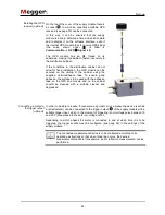
On the top of the cover of the supply module there is
a socket
, to which an optionally available GPS
received (see page 10) can be connected.
In this way, it can be ensured that the supply
module is able to determine time and position data
and to display it on the software interface, even if
the internal GPS module fails to receive GPS signal
(the value shown under
Info
Communication
GPS
Signal
is
0
).
The GPS module has an M8 thread on its
underside, making it possible to fasten it securely to
the distribution cabinet.
If the conditions in the distribution cabinet do not
allow for fixed installation, the GPS module can be
secured on the ceiling of the cabinet using the
supplied Velcro/adhesive tape. To ensure good
adhesion, the surfaces to be used with the adhesive
tape on the GPS and module and on the cabinet
should be cleaned with a suitable cleaner and
degreased.
In order to be able to locate, for example, a sporadic error a measuring device (such as
a reflectometer) can be connected to the trigger output
of the supply module with a
suitable trigger input, which in the moment of triggering (short voltage pulse between 15
and 20 V) measures into the safe low-voltage circuit.
Depending on which phases the meter is connected to and at which time it is to be
triggered, the trigger events must be configured (see page 54) in the settings of the
supply module.
The connected measurement device is to be configured according to its
operating instructions so that when triggering occurs, the desired
measurement procedure (for example, an arc reflection measurement) can be
performed.
Installing the GPS
receiver (optional)
Connecting a meter to
the trigger output
(optional)


