OMM 1008-1
11
Table 1, pLAN address and DIP Switch Settings for Controllers Using pLAN.
Chiller
(1)
Comp 1
Controller
Comp 2
Controller
Unit
Controller
Reserved
Operator
Interface (2)
Reserved
Dec.
1
2
5
6
7
8
A
Bin.
100000
010000
101000
011000
N/A
000100
Dec.
9
10
13
14
15
16
B
Bin.
100100
010100
101100
011100
N/A
000010
NOTES for pLAN multi-chiller communication setup:
1.
Two Magnitude units can be interconnected.
2.
Operator Interface Touch Screen (OITS) setting is not a DIP switch setting. The OITS address is selected by
selecting the ‘service’ set screen. Then, with the Technician level password active, select the ‘pLAN Comm’
button. Buttons A(7), B(15), C(23), D(31) will appear in the middle of the screen, then select the letters for
the OITS address for the chiller that it is on. Then close the screen. Note that A is the default setting from
the factory.
3.
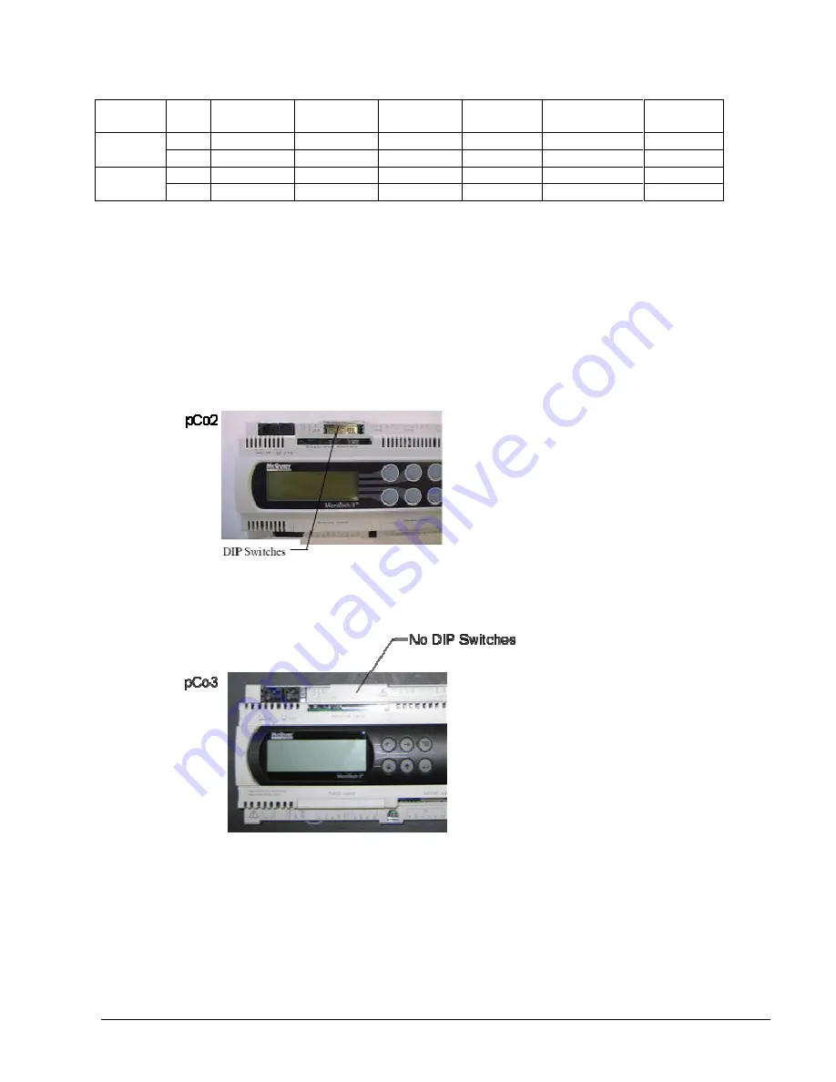
For the pCo2 controller, the pLAN address can be confirmed by viewing the DIP switch positions and
comparing to the table above (Bin. rows). There are six Binary DIP Switches: Up is ‘On’, indicated by ‘1’.
Down is ‘Off’, indicated by ‘0’. They are slide and not rocker switches.
4.
For the pCo3 controller, there are no DIP switches as shown below.
The pLAN address can only be confirmed as follows:
A) Disconnect pLAN (connectors J10 and J11) from all pCo2 and pCo3 controller(s).
B) Cycle power to the controller and then hold down both the Left Arrow (alarm) and the Up Arrow keys simultaneously
as the controller completes its Self-Test routine. The controller will then show you the present pLAN address of
the controller. Verify that the pLAN address matches the desired address from the above table (Dec. rows). If the
address needs to be changed, follow the instructions displayed on the pCo3 controller’s LCD display. Press enter
when done.
C) Only after all controllers pLAN addresses have been set/confirmed can the pLAN network connectors be re-
connected.


