68
AGZ 035A through 065A
IOMM AGZ-3
Menu #6:
Circuit 62 Pressures
The circuit #2 evaporator and condenser refrigerant pressure
readings are displayed under this menu. The calculated minimum and maximum condenser pressure
values are also shown.
Menu #7
: Circuit #l Temperatures
The circuit #I refrigerant temperatures are calculated from their
corresponding pressure sensors and displayed here. If the optional Sensors are not present, the line
item will flash “Open”.
Menu #8
: Circuit #2 Temperatures
The circuit #2 refrigerant temperatures are calculated from their
corresponding pressure sensors and displayed here. If the optional sensors are not present, the line
item will flash “Open”.
Menu#9:
Chiller Amps
Displays the present amp draw of the chiller expressed as a percentage of
the unit rated load amps under full load conditions (optional feature).
Menu #10:
Compressor Run Hours
The total run hours for each compressor is available under this
menu.
Menu #11:
Compressor Starts
The total number of starts for each compressor is available under this
menu.
Menu#12:
Air Temperature
Displays the current outdoor air temperature if the optional OAT sensor
is installed on the air cooled chiller and “Lcl” is selected from Menu 23. Also displayed here is the
air temperature received from a network if the “Rmt” OAT select option from Menu 23 is selected.
Control Menus
Menus 13 through 23 are the set point menus. All adjustable control parameters and set points, time
schedules, control options, and alarm thresholds are accessed through these menus.
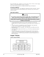
CAUTION
Any changes to these parameters must be determined and implemented by
qualified personnel with a thorough understanding of how these parameters
affect the operation of the unit. Negligent or improper adjustment of these
controls can result in damage to the unit or personal injury.
Menu #13:
Control Mode
One of several automatic and manual operating modes can be selected
from within this menu. Typically, the selected control mode will be Automatic which will allow the
MicroTech controller to handle all compressor and condenser fan staging. Refrigerant circuit #2 can
be locked off while still allowing circuit #1 to stage automatically by selecting AutoCir#1 -Off#2 as
the operating mode. OffCirc#1 -Auto#2 allows the normal staging of refrigerant circuit #2 but circuit
#1 is locked off. Select Manual Staging if manual control is desired. In this operating mode, the
condenser fans are controlled by the MicroTech but the number of stages is determined manually via
the keypad. If manual staging is selected, the second item under this menu indicates the number of
active cooling stages. Use the INCR or DECR keys to increase or decrease the number of active
stages.
Menu#14:
Leaving Water Set Points
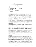
The leaving wafer set points, control band, maximum pull
down rate and water reset options are adjusted from this menu. The first menu item is The Active Set
Point ("Active Spt"). The current control temperature is displayed here. The Leaving Chilled Water
Set Point ("Lvg Evap") appear towards the top of this menu. These are the set points that will be
maintained for chillers if no reset options are in effect. The Active Control Set Point ("Active Spt")
will display the calculated chilled or heated water temperature to be maintained when one of the reset
options is enabled.
If the 4-20 milliamp reset option is enabled, the controller will reset the leaving chilled water
temperature to a higher value based on a percentage of the Maximum Chilled Water Reset set point
("MaxChWRst"). At 4ma or less, no reset will occur. At 20ma, the chilled water set point will be reset
Содержание AGZ 035A
Страница 6: ...6 AGZ 035A through 065A IOMM AGZ 3 Figure 3 Clearance Requirements...
Страница 18: ...18 AGZ 035A through 065A IOMM AGZ 3 Electrical Legend Figure 8 Electrical Legend...
Страница 19: ...IOMM AGZ 3 AGZ 035A through 065A 19 Figure 9 Typical Field Wiring with Global UNT Controller...
Страница 20: ...20 AGZ 035A through 065A IOMM AGZ 3 Figure 10 Typical Field Wiring Diagram with MicroTech Controller...
Страница 21: ...IOMM AGZ 3 AGZ 035A through 065A 21 Figure 11 Single point Connection with FanTrol...
Страница 22: ...22 AGZ 035A through 065A IOMM AGZ 3 Figure 12 Single point Connection with SpeedTrol...
Страница 23: ...IOMM AGZ 3 AGZ 035A through 065A 23 Figure 13 Unit Control Schematic UNT...
Страница 24: ...24 AGZ 035A through 065A IOMM AGZ 3 Figure 14 Staging Schematic UNT...
Страница 25: ...IOMM AGZ 3 AGZ 035A through 065A 25 Figure 15 MicroTech Controller Schematic...
Страница 26: ...26 AGZ 035A through 065A IOMM AGZ 3 Figure 16 Unit Control Schematic MicroTech...
Страница 27: ...IOMM AGZ 3 AGZ 035A through 065A 27 Figure 17 Staging Schematic MicroTech...
Страница 94: ...94 AGZ 035A through 065A IOMM AGZ 3 Notes...
Страница 95: ......


